Hydrogen Duty
Normal/peak output, operating hours, pressure/purity point, storage or process interface and redundancy.

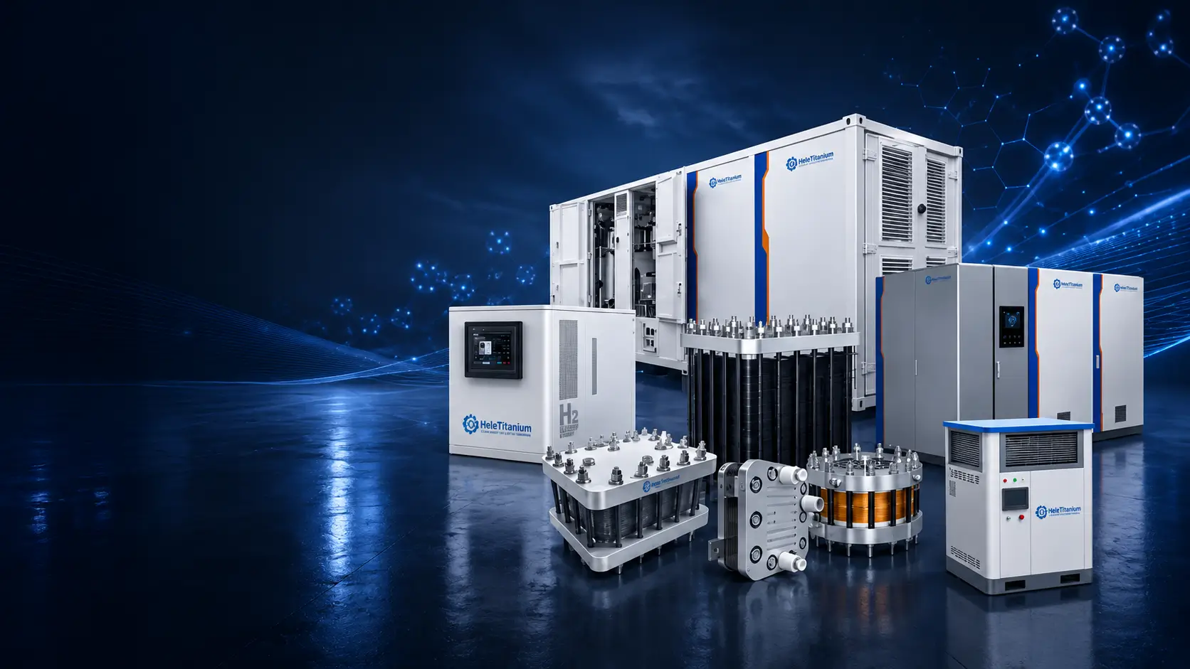
PEM Electrolyzer Systems · Stack, BoP, Controls & Project Integration
Project-specific PEM electrolyzer systems reviewed against hydrogen output and duty profile, power, pressure and gas-quality point, water and cooling, dynamic operation, balance of plant, controls, safety, FAT and site interfaces.
Performance boundary: output, pressure, purity, specific energy, turndown and life are meaningful only with the configuration, test point, water, temperature, duty, auxiliary-load boundary, analytical method and end point. DOE targets are technology guideposts—not HELE product guarantees.
Start with the hydrogen use case and complete operating profile. A nameplate kW value does not establish delivered hydrogen, pressure, gas quality, dynamic capability, availability or site fit.
Normal/peak output, operating hours, pressure/purity point, storage or process interface and redundancy.
Grid/renewable source, AC/DC boundary, ramp, turndown, cycling, starts/stops, availability and auxiliary loads.
Feed treatment, water-quality limits, circulation, consumption, temperature, cooling duty and waste streams.
BoP, PLC/HMI, communications, detection, shutdown, ventilation, site utilities, permitting and documentation.
Compare the S, H, C and M series with the containerized platform by hydrogen output and project format, then open the dedicated product page for the complete configuration basis. Published values describe the stated series or reference configuration; the quotation confirms operating conditions, included equipment, acceptance evidence and site interfaces.
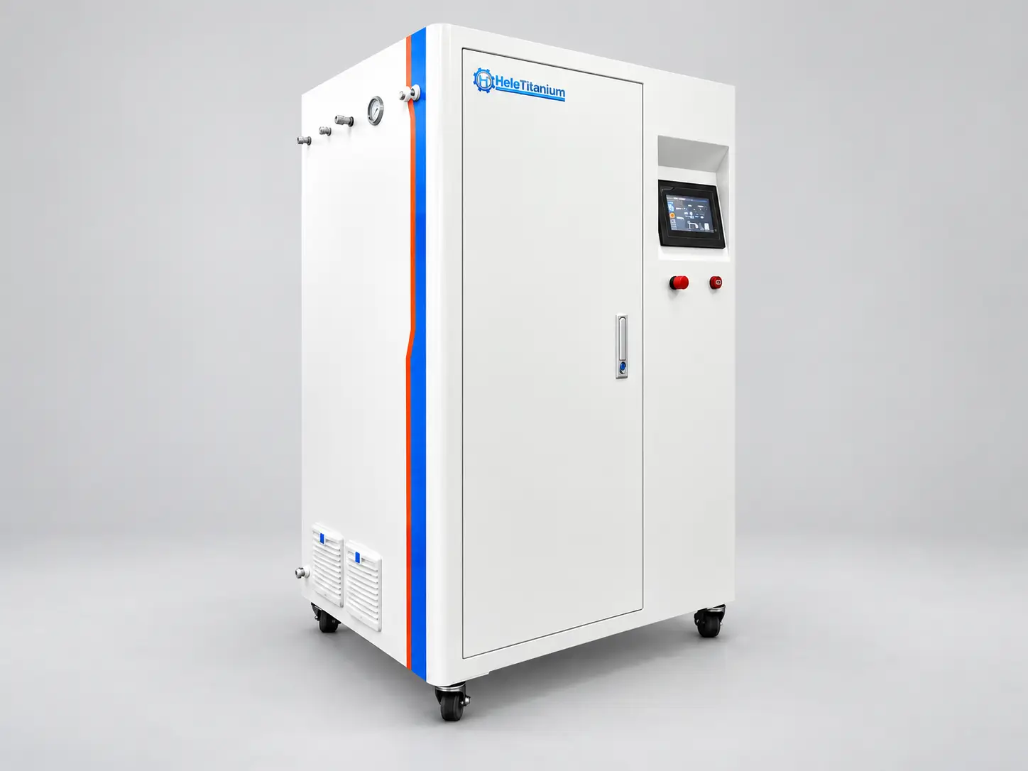
Configuration direction
Hydrogen output
0.5–1.0 Nm³/h
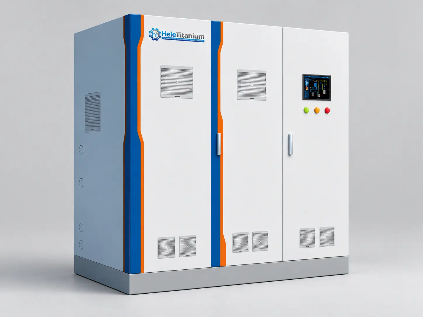
Configuration direction
Reference hydrogen output
5 Nm³/h
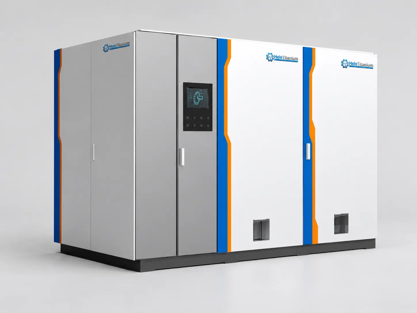
Configuration direction
Hydrogen output
6–10 Nm³/h
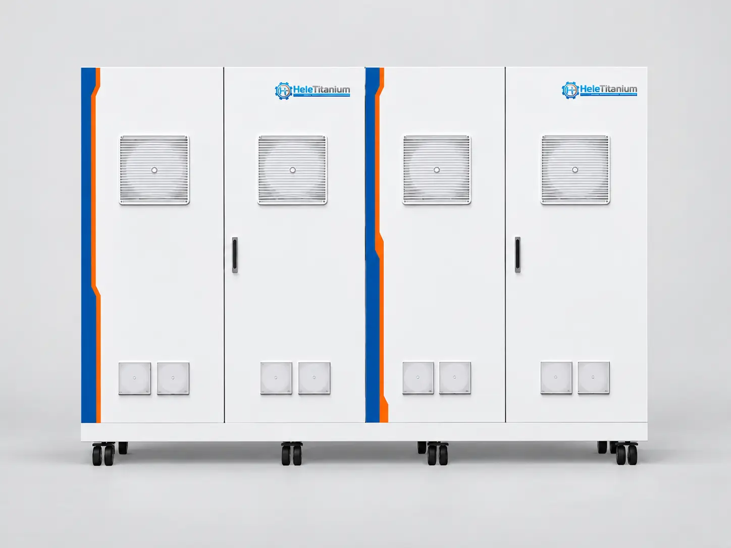
Configuration direction
Hydrogen output
10–50 Nm³/h
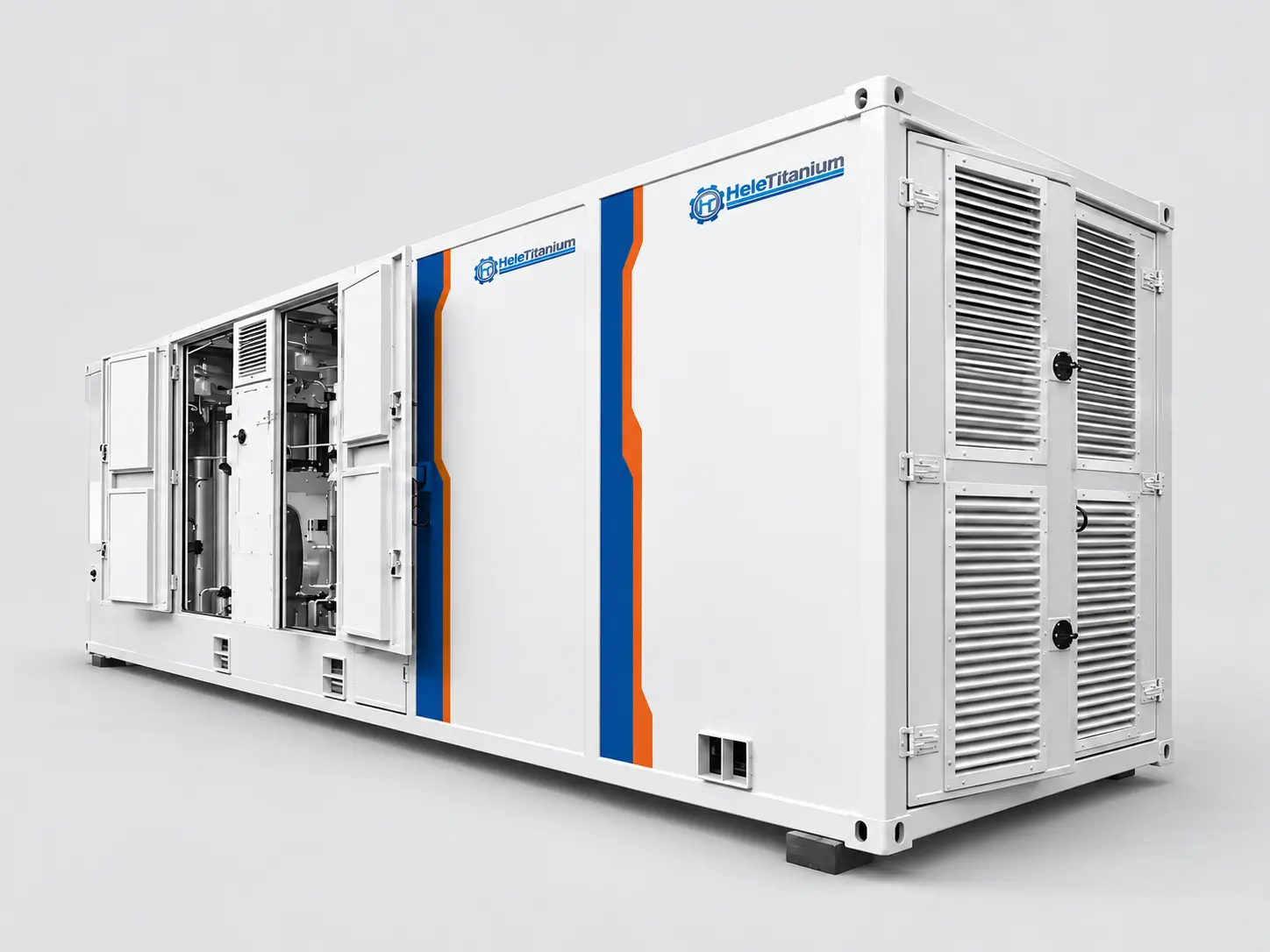
Configuration direction
Hydrogen output
50–300 Nm³/h
Selection rule: hydrogen output alone does not select the system. Confirm the reference conditions, normal and peak duty, operating profile, pressure and gas-quality point, power boundary, water and cooling, installation format and downstream responsibilities.
H-Series note: 5 Nm³/h is shown as a reference configuration. The available range and performance-test basis require project confirmation.
A stack is the electrochemical conversion core. A complete system adds the functions needed to feed, cool, separate, condition, control and protect the process. The diagram explains the relationship; the quotation must still list every included and excluded item.
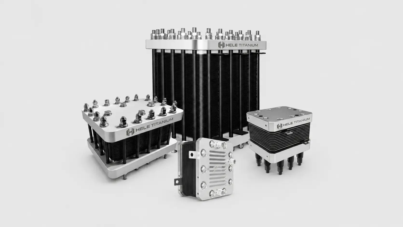
Electrochemical core
Cells, MEA-related interfaces, porous transport/current collection, bipolar/end plates, seals, manifolds and compression structure as designed.
Review PEM Electrolyzer Stacks →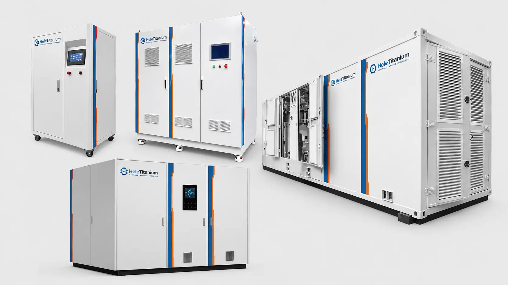
Supporting functions
Water treatment/circulation, gas-liquid separation, heat removal, rectification, instrumentation, controls, safety and optional gas conditioning.
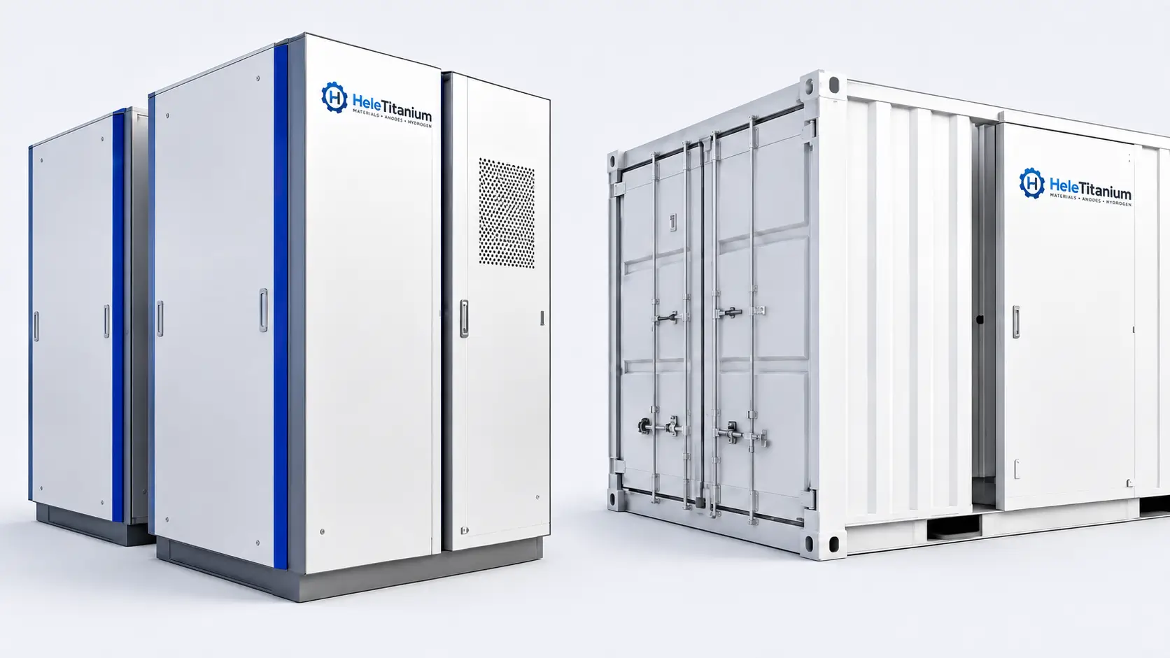
Order-defined result
Skid or container, utilities, interfaces, PLC/HMI, safety functions, FAT, manuals and order-defined site integration or commissioning support.
Stack evidenceBuild revision, interfaces and test conditions.
BoP evidenceP&ID, equipment list, controls and functional tests.
System evidenceDefined FAT boundary, results, documents and exceptions.
A useful comparison includes both the headline parameter and the measurement boundary behind it. Use this table to normalize supplier quotations before comparing output, pressure, gas quality, energy or dynamic operation.
| Parameter | Planning basis | Measurement boundary | Confirm in the order |
|---|---|---|---|
| Hydrogen production | Normal, peak and annual duty; no universal public value | Defined system outlet and stated reference conditions | Flow or mass basis, operating profile, stabilization and test duration |
| Outlet pressure | Configuration- and project-specific operating range | Named stack, separator, system outlet or downstream point | Normal/maximum pressure, differential pressure and compressor boundary |
| Hydrogen quality | Order-specific purity, dew point and impurity limits | Named sampling point before or after conditioning | Separator, dryer/purifier scope, method, calibration and off-spec handling |
| Energy consumption | Stack DC or complete-system AC basis | Declared electrical meter and hydrogen measurement boundary | Rectifier and auxiliary loads, load point, reference conditions and duration |
| Dynamic operation | Defined turndown, ramp, standby and start/stop sequence | Stack, rectifier, BoP and control-system boundary | Renewable profile, thermal state, acceptance cycle and protection limits |
| Availability and life | Evidence-based project basis rather than an unconditional claim | Specified stack/system configuration and operating history | Maintenance, replacement, degradation/end-of-life method and warranty exclusions |
Important: a public family name or reference configuration is not a guaranteed operating envelope. Final values belong in the quotation, approved datasheet and FAT basis for the selected configuration.
Unknown inputs can remain open. They should not be replaced by generic model, purity, pressure or life claims.
Hydrogen flow/mass, normal and peak duty, hours, availability, turndown, ramp and cycling.
Pressure and sampling point, purity, dew point, oxygen/crossover limits, drying/purification and storage/use boundary.
Electrical source, water, cooling, drainage, ventilation, ambient, altitude, layout, hazardous-area and communications.
Jurisdiction, applicable standards, certification route, FAT/witness, documents, Incoterm, schedule and installation scope.
HELE can review the project duty and coordinate an order-specific PEM electrolyzer supply around the approved performance basis, equipment list and responsibility matrix. The quotation identifies what is included, optional or excluded, and the signed order documents define the final supply boundary.
01 · Requirement Review
Review hydrogen output and reference conditions, gas-quality point, delivery pressure, operating profile, power, water, cooling and site constraints.
Typical output: design-basis summary and open-item list for quotation.
02 · System Configuration
Coordinate stack or module selection with the rectifier, water circulation, gas-liquid separation, cooling and gas-conditioning boundary.
Typical output: proposed configuration and preliminary supply-scope schedule.
03 · Skid & BoP Integration
Review water, hydrogen, oxygen, cooling, drain, vent, purge, relief and mechanical interfaces against the agreed package boundary.
Typical output: agreed PFD/P&ID, GA or interface documents when included.
04 · Electrical & Controls
Coordinate the rectifier boundary, PLC/HMI, instruments, communications, permissives, alarms, shutdowns and detection interfaces specified for the package.
Typical output: interface list, control narrative or I/O documentation as agreed.
05 · FAT & Evidence
Perform only the agreed leak, pressure, functional, interlock and performance checks under documented test conditions and measurement boundaries.
Typical output: FAT, inspection and release records listed in the order.
06 · Delivery Support
Align manuals, drawings, certificates, preservation, packing, recommended spares and any remote or site-support option before release.
Typical output: approved document register and handover package.
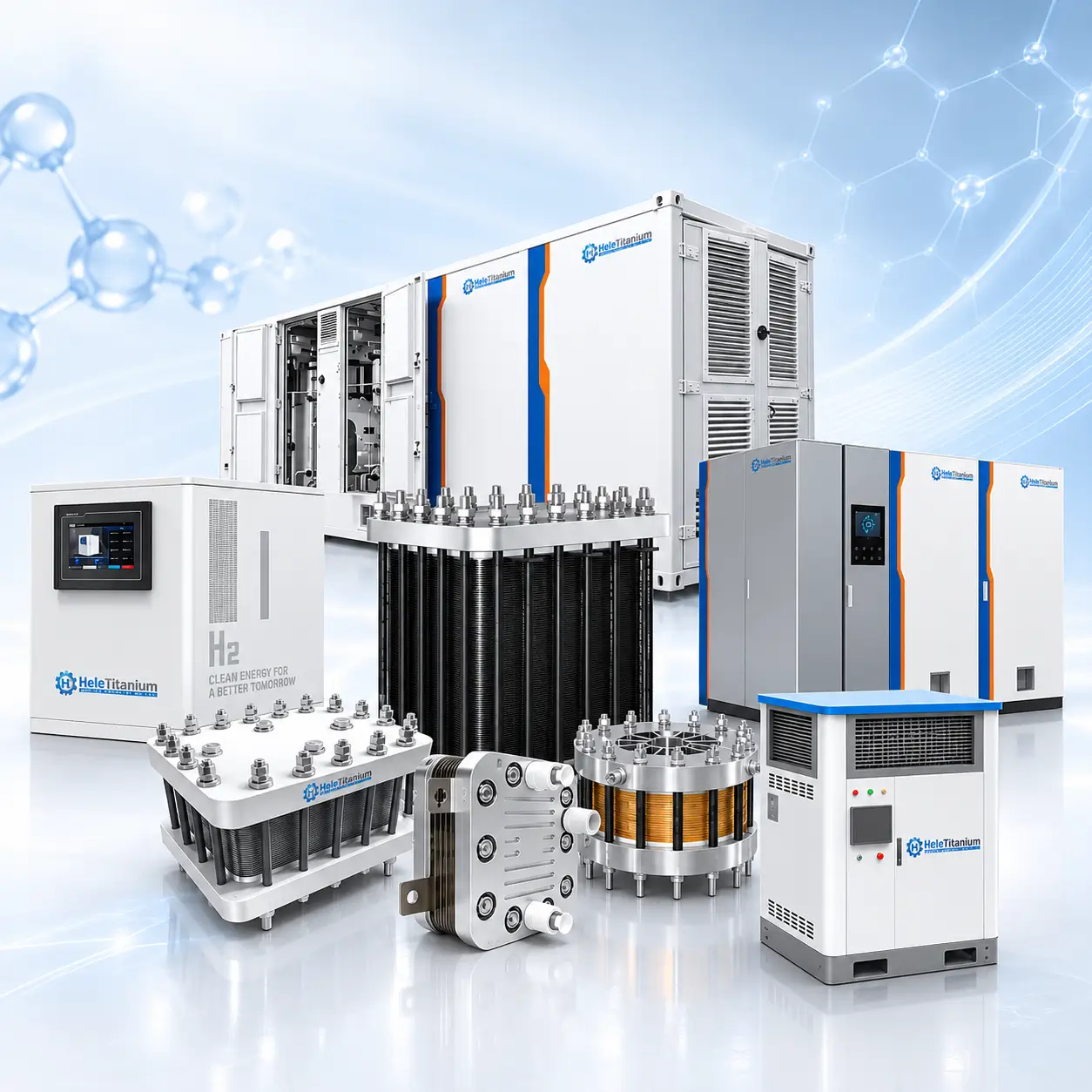
A packaged electrolyzer image does not prove that every downstream or site item is included. Mark each item as included, optional, customer-supplied or excluded in the approved responsibility matrix.
Order rule: only the signed quotation, approved equipment list, drawings and responsibility matrix define the final HELE supply.
Application names route the inquiry; actual configuration depends on production profile, gas delivery, utilities, site and downstream integration.
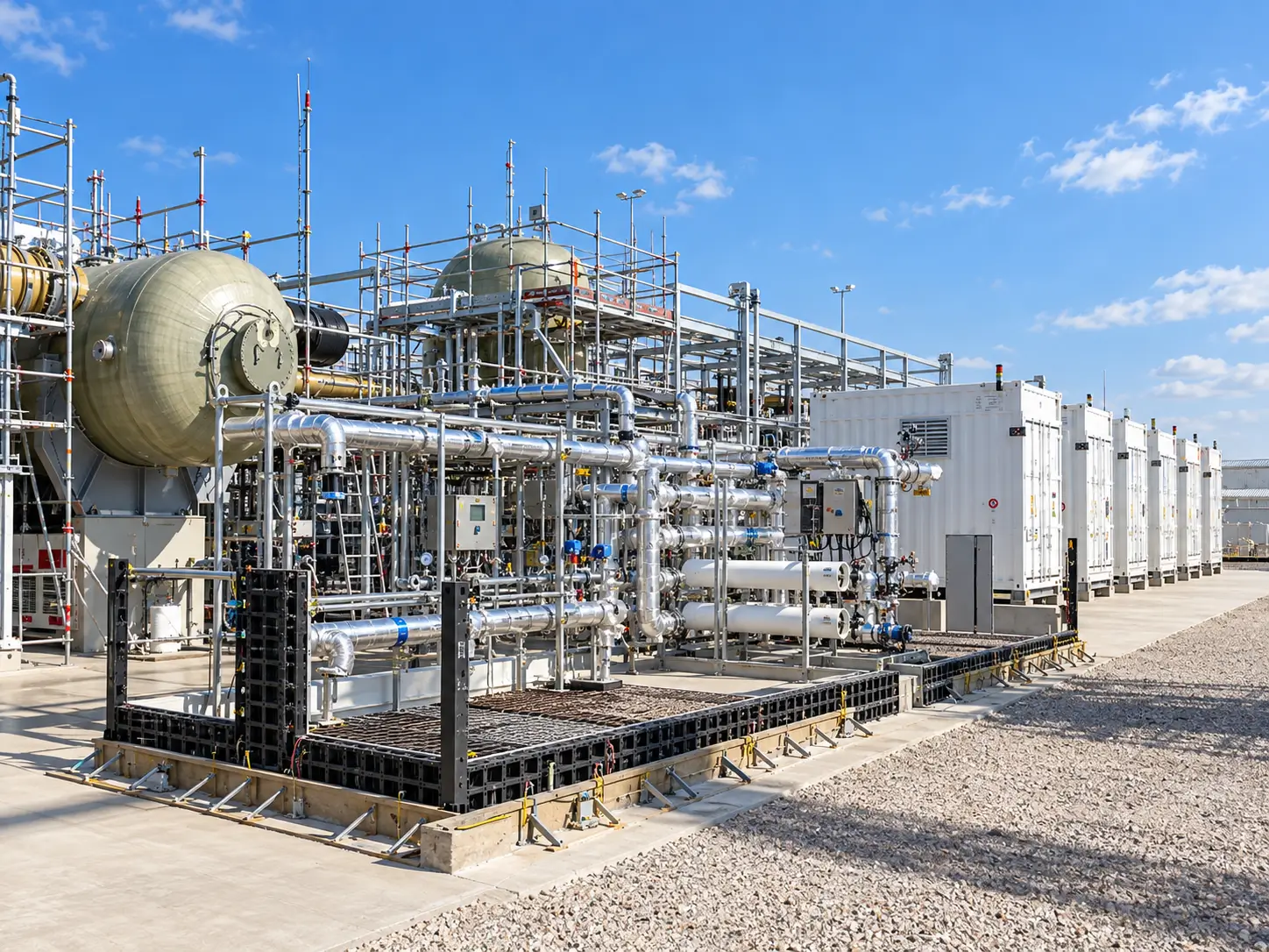
Define production rate and profile, pressure/purity point, storage/use interface, utilities, redundancy and permitting.
Provide generation/load profile, rectifier/DC interface, ramp and cycling, curtailment strategy, availability and degradation basis.
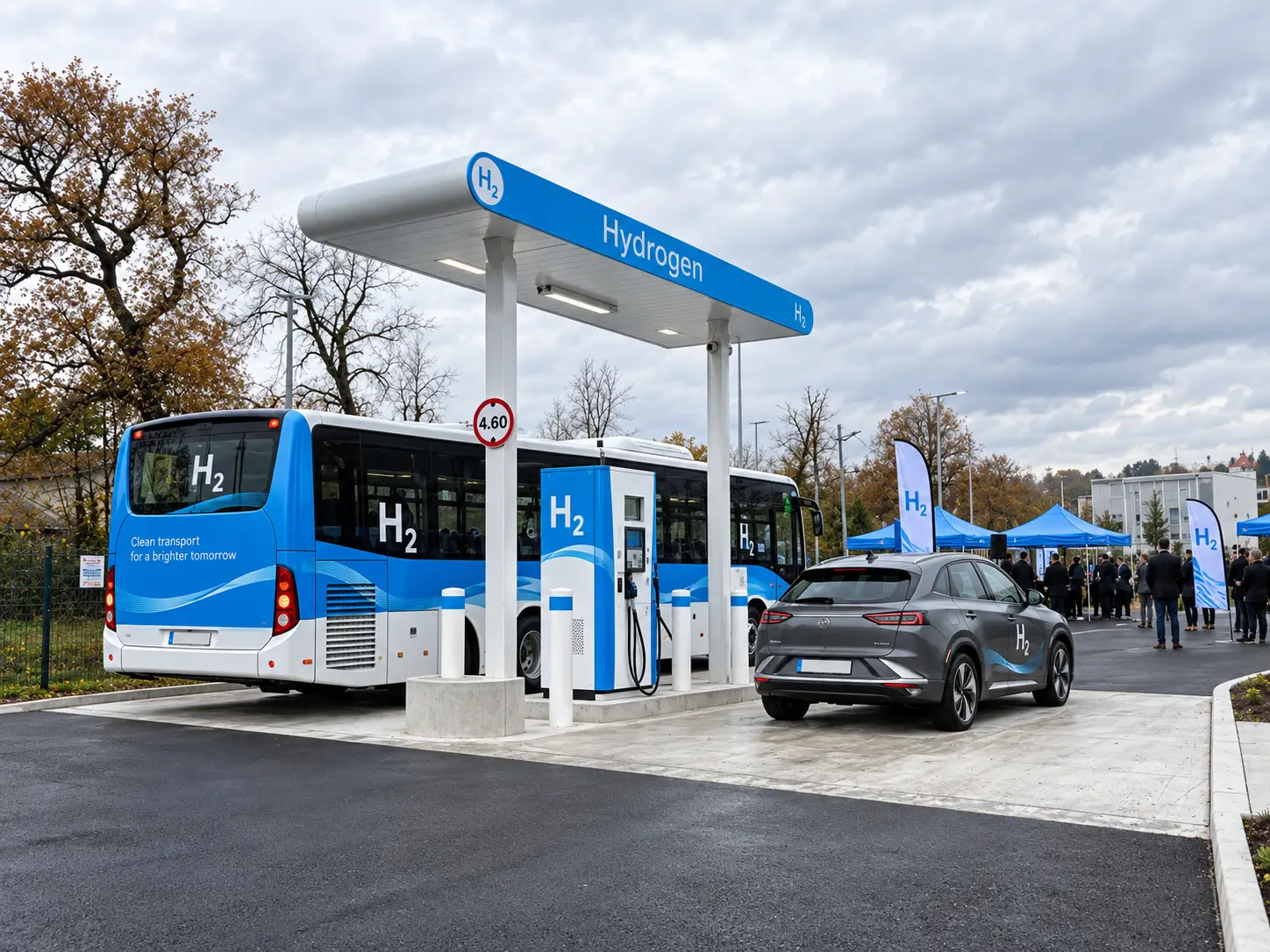
Separate electrolyzer production from drying, compression, storage, cooling and dispensing responsibilities.
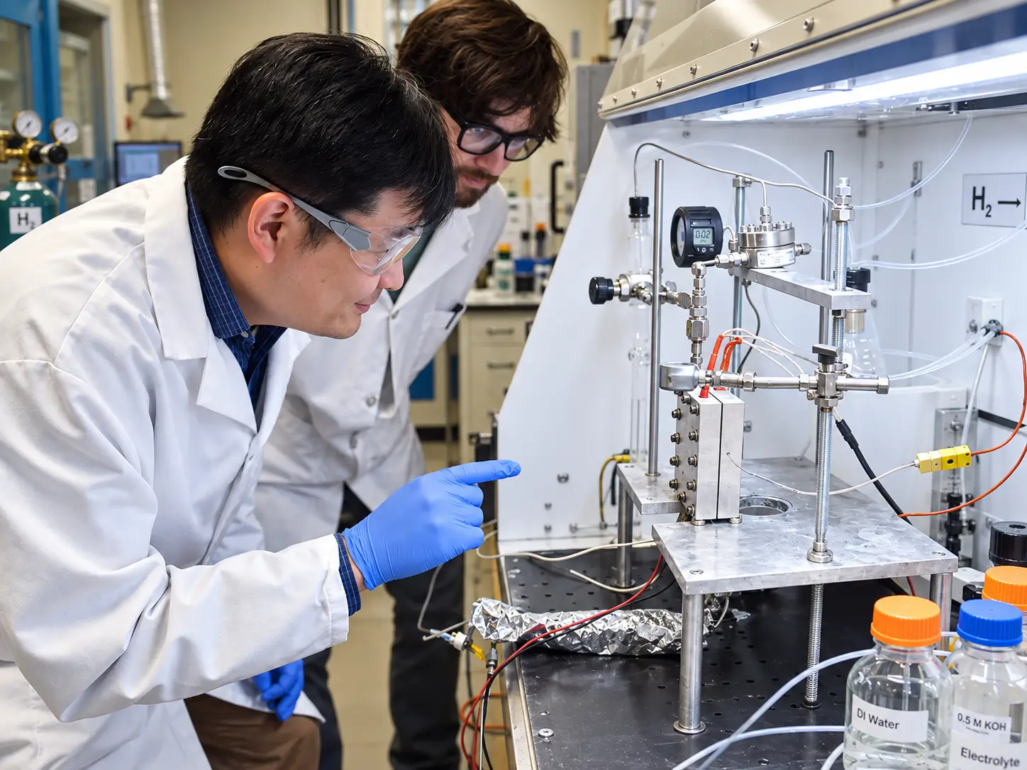
Control test objective, data acquisition, safe installation, sample points, operating envelope and scale-up boundary.
FAT scope must state the configuration, utilities, measurement points, instruments, duration, acceptance and deviations. A witnessed function test is not automatically a long-duration performance or field-life demonstration.
| Control | Order definition | Evidence when included |
|---|---|---|
| Hydrogen duty | Normal/peak output, operating hours, turndown, ramp, starts/stops and availability | Sizing sheet and order-specific performance/FAT basis |
| Electrical | AC input or DC boundary, rated power/current/voltage, rectifier and auxiliary loads | Electrical drawings and measured FAT data |
| Gas delivery | Pressure and measurement point, purity, dew point, separator/dryer/purifier and downstream boundary | Defined sampling and analytical method |
| Water & thermal | Feed treatment, water-quality limits, consumption, circulation, temperature and cooling duty | P&ID, water specification and operating/manual limits |
| BoP & controls | Pumps, separators, heat exchangers, valves, instruments, PLC/HMI, communications and alarms | I/O list, cause-and-effect and functional test |
| Safety & documents | Relief/vent, detection, ventilation, shutdown, applicable standards, manuals and data book | Approved safety/FAT/document package |
Medium, boundary, pressure, duration, temperature, instrument and acceptance.
Hydrogen, power, water, temperature, pressure, auxiliaries, duration and normalization.
Sampling point, conditioning state, method, calibration, purity/dew point and limits.
Interlocks, alarms, shutdown, detection, relief/vent, communications and recovery.
The route shown is an overview. Actual ownership of component manufacture, stack build, system integration and testing must match the approved supply chain and order records.
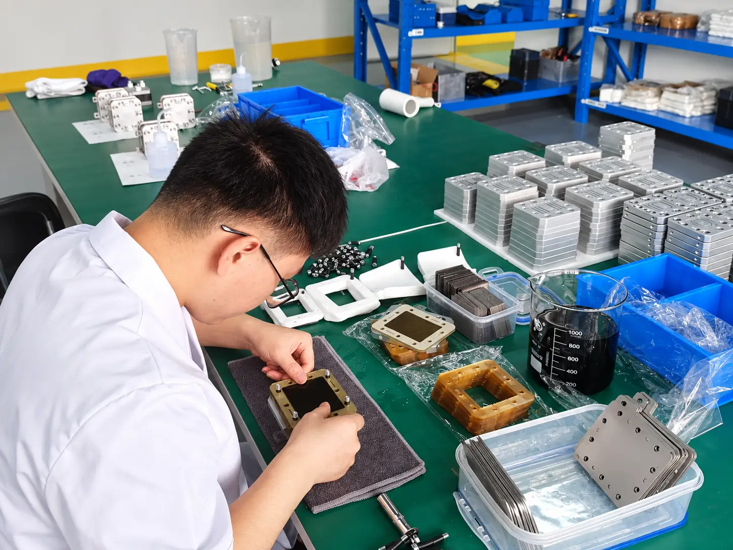
Confirm approved components, material/lot identity, cleanliness, handling and build documentation.
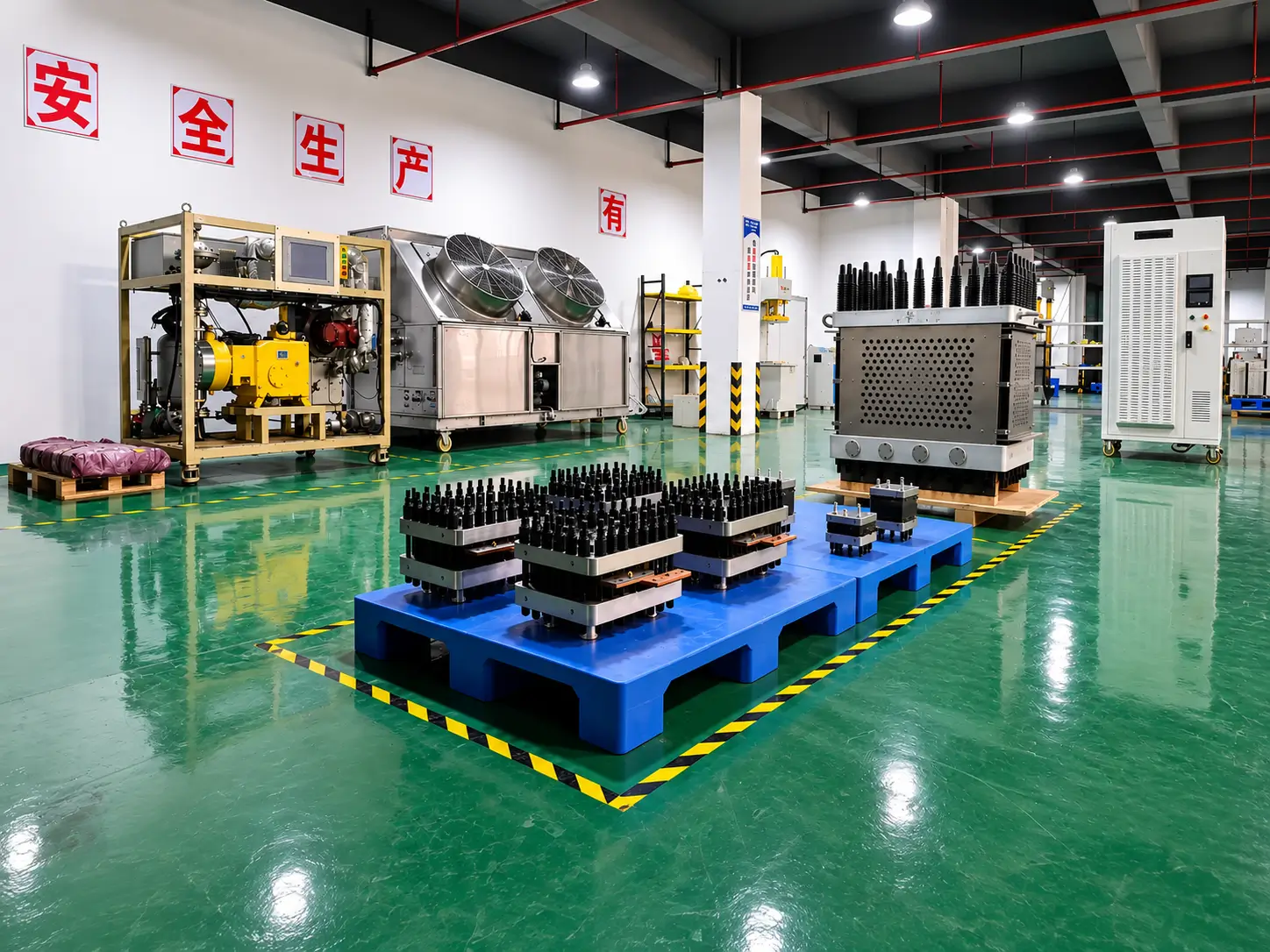
Control stack build revision, interfaces, compression/sealing route and in-process inspection.
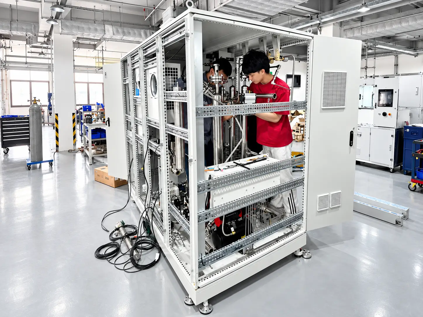
Integrate water, gas, cooling, power, controls, instrumentation and safety functions to the approved P&ID and drawings.
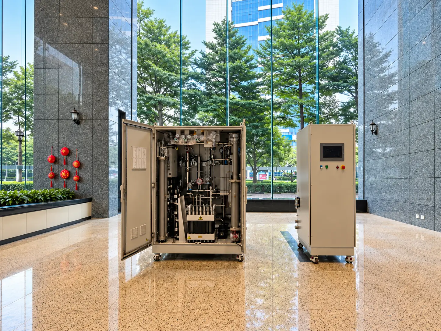
Complete the agreed FAT, leak/pressure, functional, documentation, preservation and packing release.
PEM electrolyzer comparisons must separate stack performance from packaged-system performance and use the same hydrogen, purity, pressure, operating profile, utilities, safety and acceptance basis.
The quotation should identify stack, rectifier or DC supply, water treatment and circulation, gas-liquid separation, drying or purification where included, cooling, controls, instrumentation, safety systems, skid or container, tests, documents and excluded balance-of-plant items.
No. State normal/rated power and current, operating temperature and pressure, water quality, measurement point, reference conditions, gas purity or dew-point method, auxiliary loads and test duration.
No. Stack voltage or specific energy excludes some or all balance-of-plant loads. System energy must state rectifier, pumps, cooling, drying, controls and measurement boundary.
No. Define pressure at the stack or system test point, gas-liquid separation, drying/purification, relief and downstream compression or storage responsibility.
State feed-water source and treatment, conductivity/resistivity, TOC and ionic limits where applicable, temperature, flow, consumption, storage, sampling and monitoring.
ISO 22734-1:2025 is a current safety standard for hydrogen generators using water electrolysis. Applicability, edition, certification route and project/jurisdiction requirements must be confirmed for the ordered configuration.
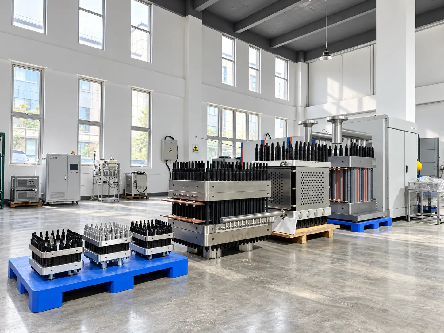
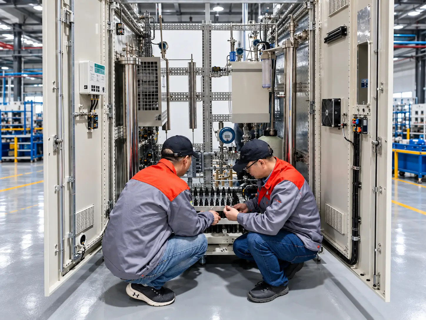
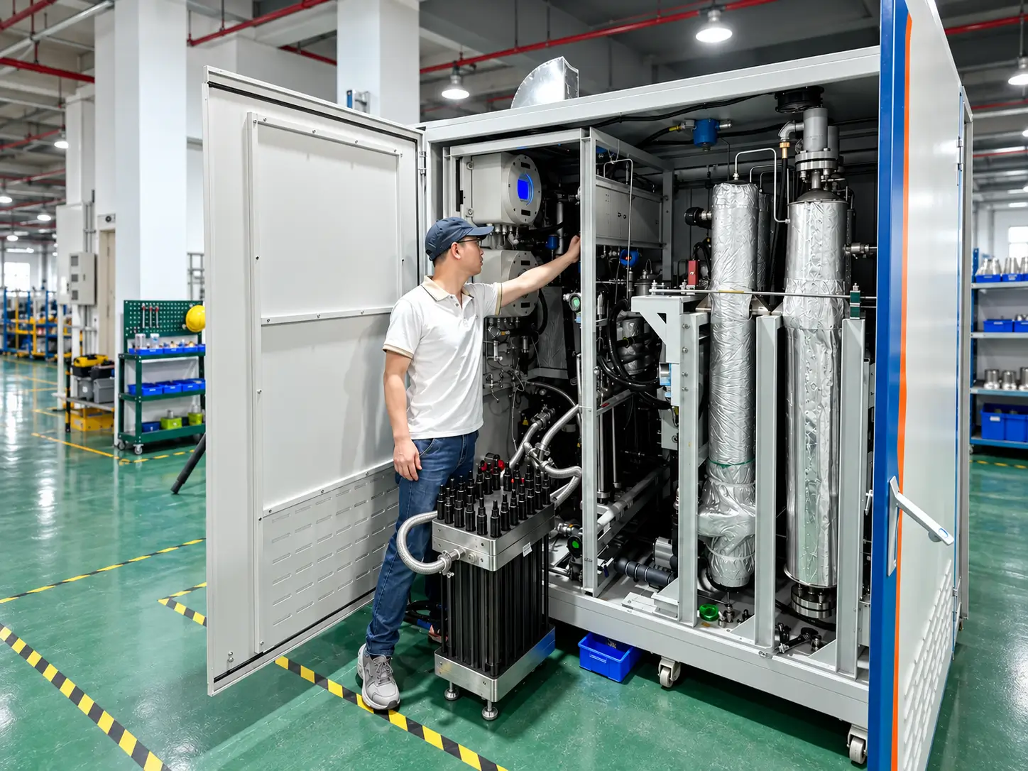
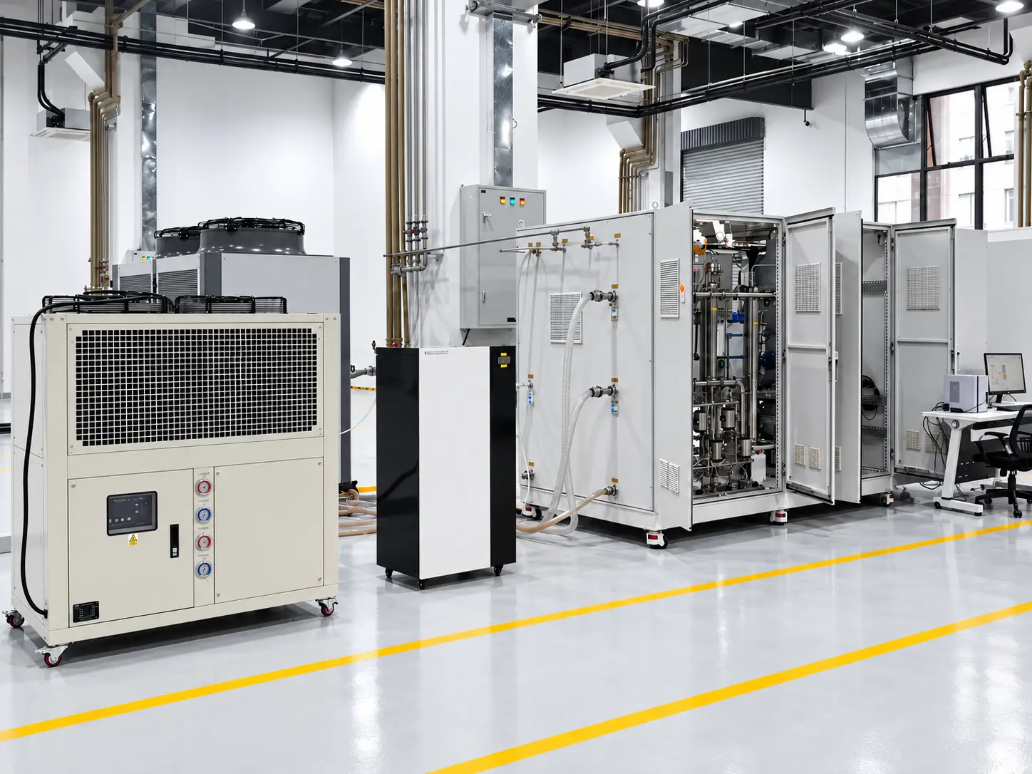
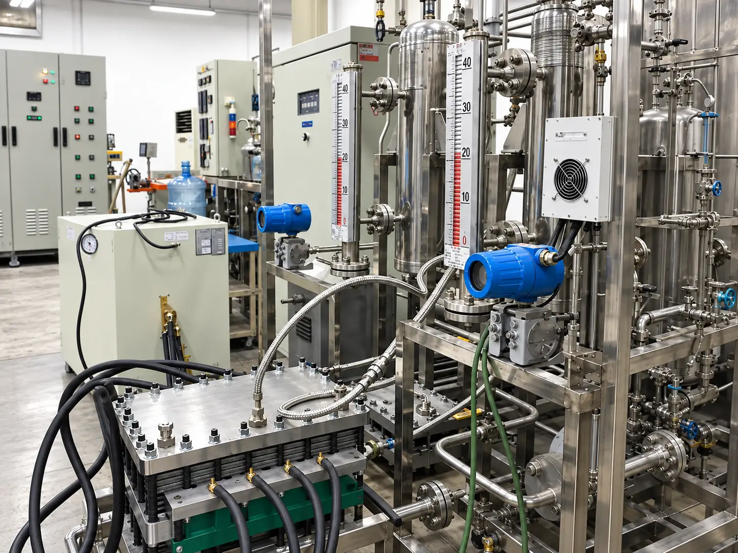
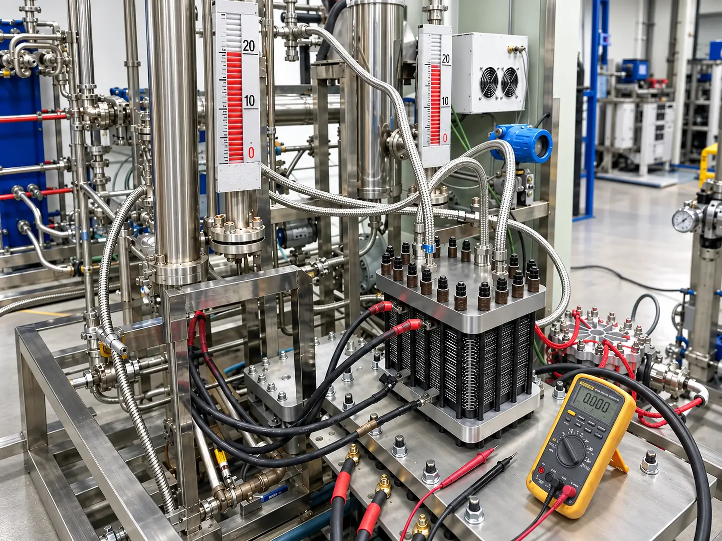
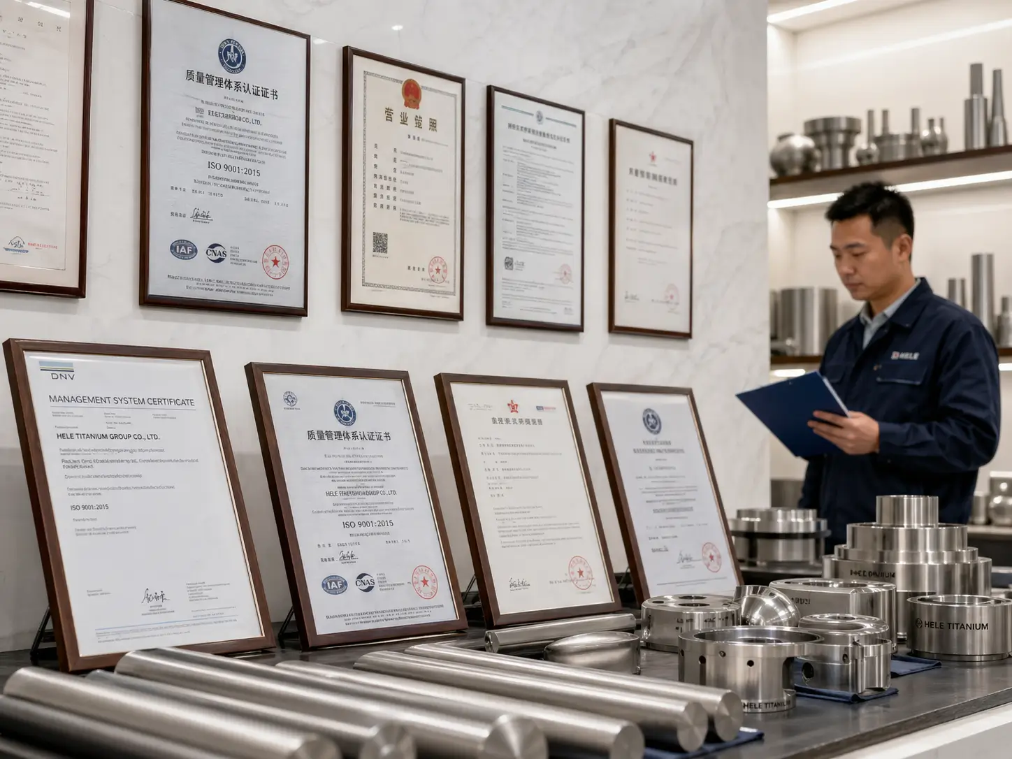
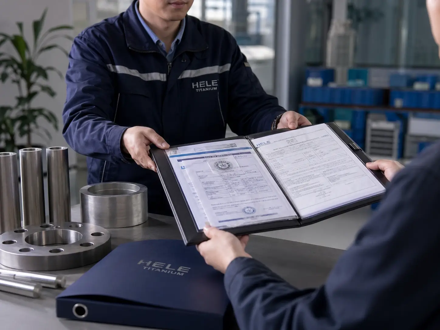
A visual overview of the assembly, system-integration, inspection, documentation and release environment. The exact manufacturing ownership, tests and records for an order are confirmed in the quotation, approved quality plan and supply-chain documentation.
Send the project information already available. Unknown items can remain open for review rather than being replaced by an unconditioned model, pressure, purity or life claim.