Grid layout
Ribbon conductors and cross-connections can form a distributed network across the tank footprint.

Tank Bottom ICCP · Under-Tank MMO Anodes
A tank-bottom ICCP layout must deliver current across the external steel bottom within the actual foundation or interstitial space. HELE can supply ribbon, mesh-ribbon, wire or linear anodes to the approved grid, ring or zone drawing.
Tank diameter alone does not determine anode length, spacing, output or life. Foundation layers, liner, coating condition and monitoring access must be included.
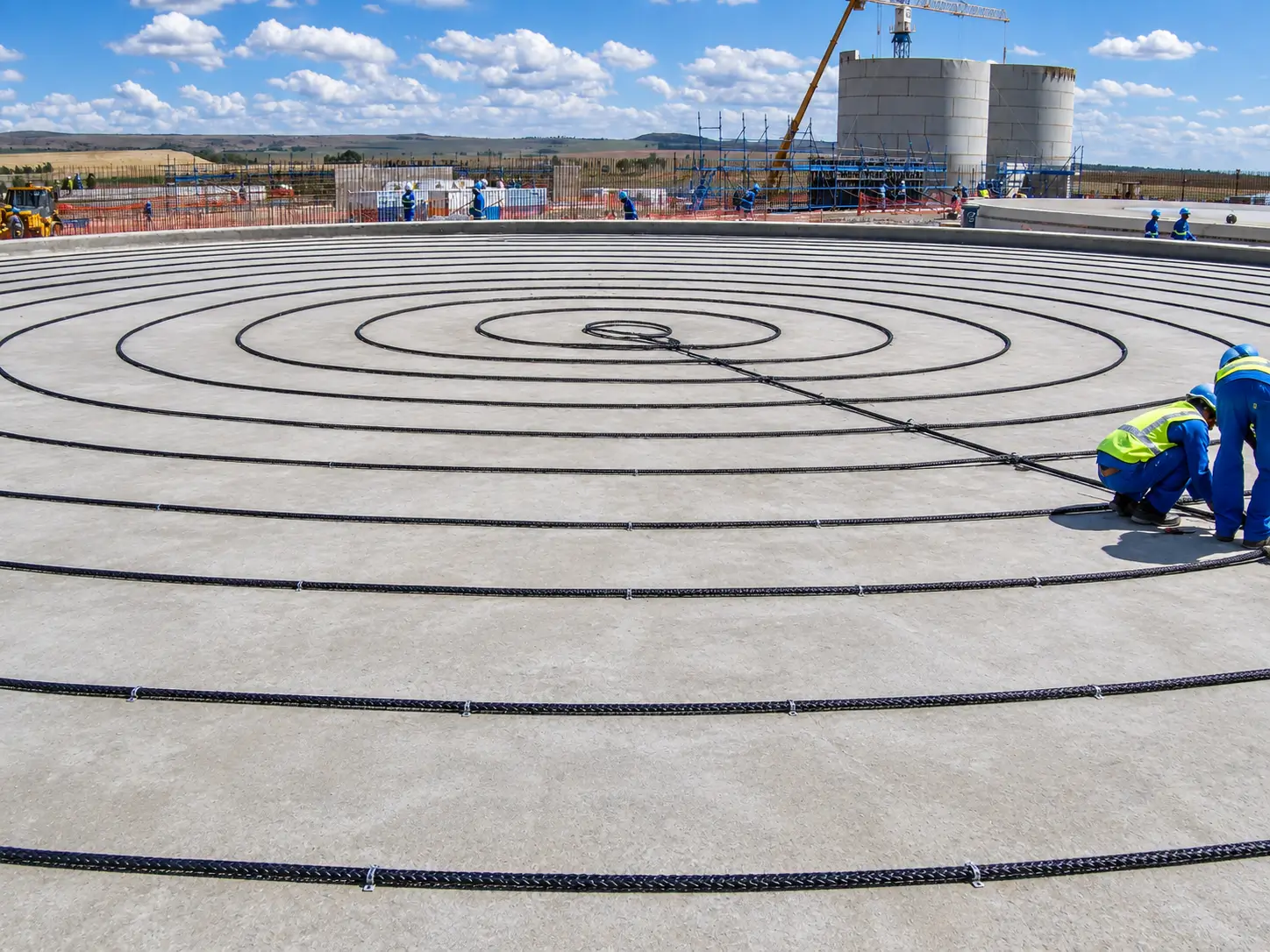
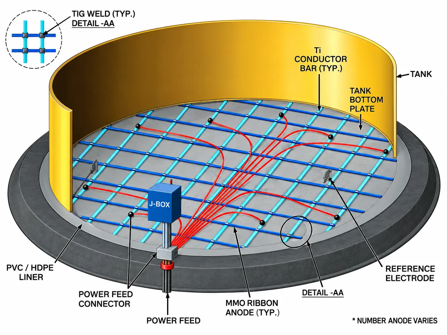
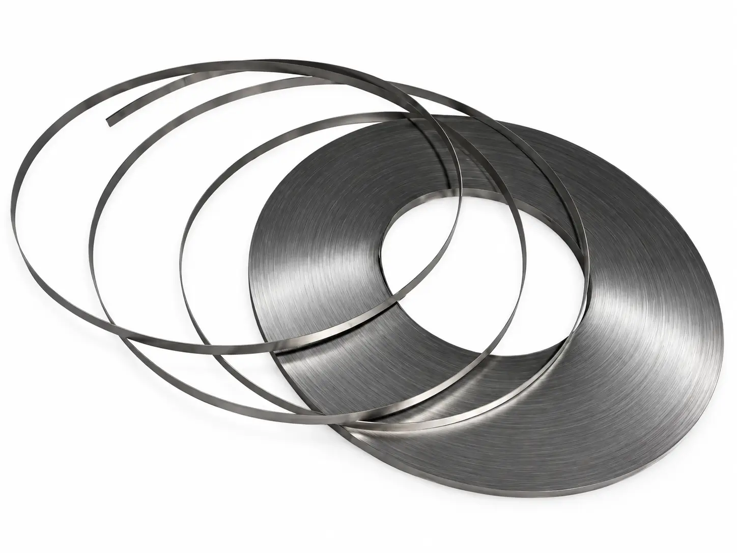
An under-tank ICCP system distributes protective current across the external surface of the steel bottom. MMO ribbon, mesh-ribbon, wire or linear anodes are installed in the foundation or interstitial space according to the approved geometry, while reference electrodes and monitoring points support commissioning and long-term control.
The layout must account for foundation resistivity, sand pad, liner or membrane, tank-bottom coating, replacement-bottom geometry, electrical continuity and construction sequence. HELE supplies the agreed anode components and assemblies; the tank CP designer confirms zoning, current demand and monitoring strategy.
Select the distribution pattern from tank geometry, foundation construction, installation timing and current-distribution model.
Ribbon conductors and cross-connections can form a distributed network across the tank footprint.
Expanded or mesh-ribbon elements can provide a low-profile distributed arrangement with specified connection details.
Linear or wire anodes can be routed in rings to suit a circular tank and project-defined zoning.
The interstitial geometry, spacer arrangement, penetrations and monitoring access control constructability.
The preferred form must be tied to the installation drawing, crossing or splice design, cable routing and foundation method.
Best considered when: a low-profile grid or ring element is specified for controlled routing beneath the tank.
Confirm: ribbon width/thickness, coating/loading, crossing connections, leaders and termination.
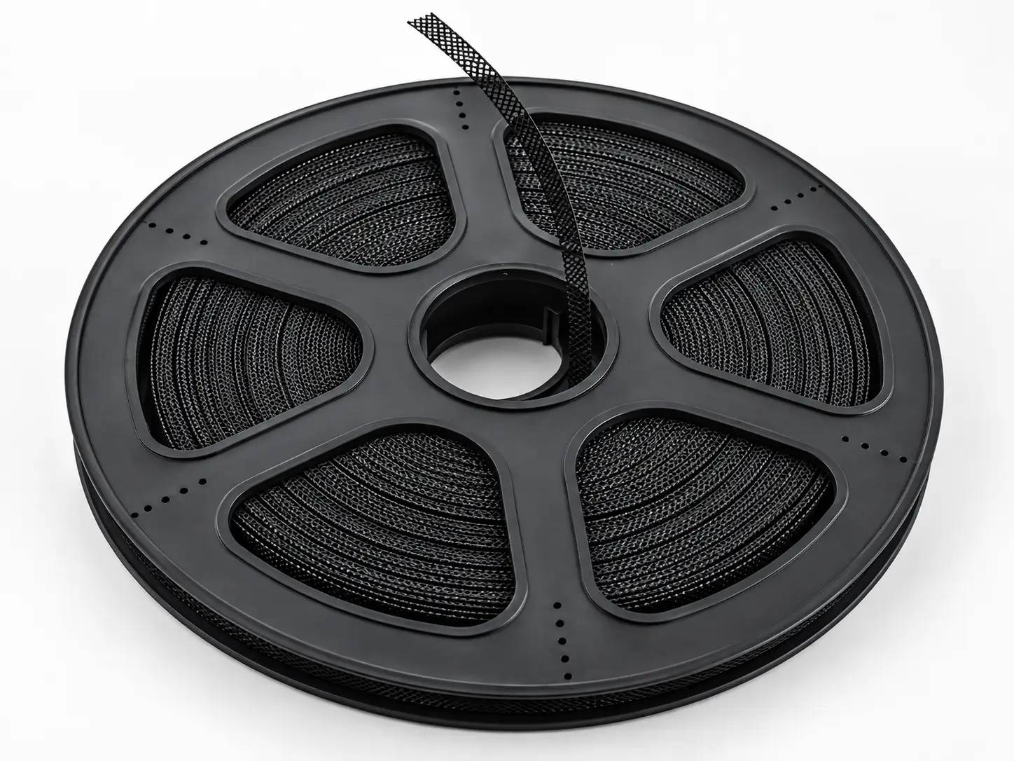
Best considered when: a distributed mesh element suits the approved foundation or interstitial layout.
Confirm: mesh geometry, connection tabs, layout panels, joints and placement method.
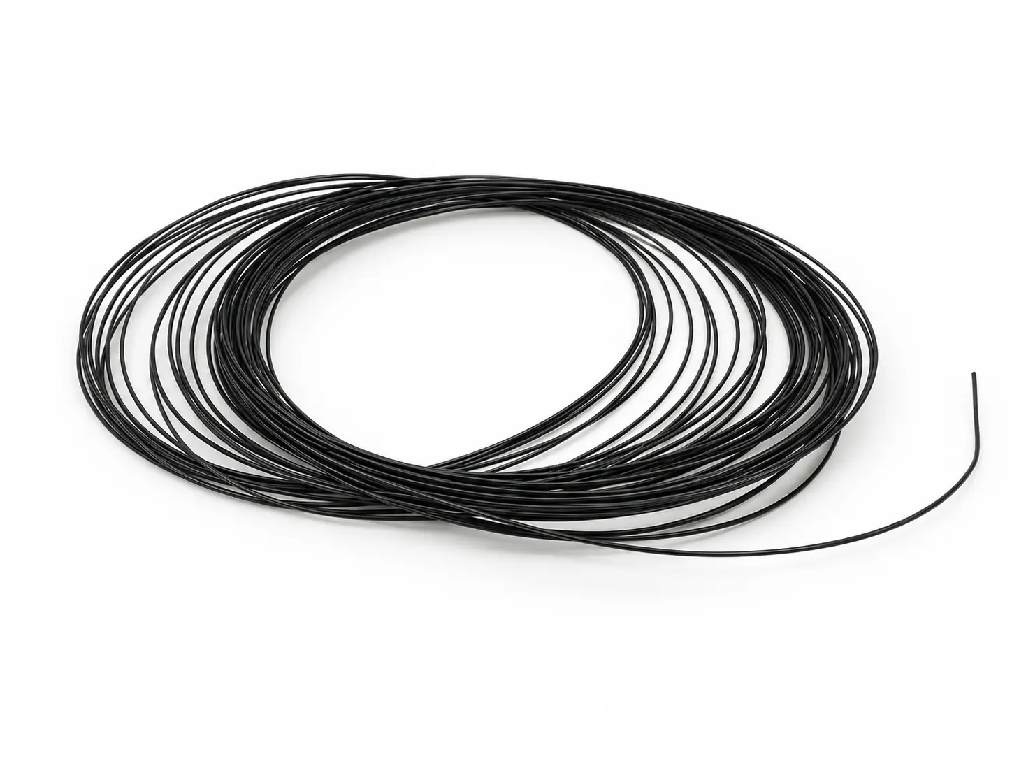
Best considered when: a flexible anode route is needed for rings, perimeter runs or localized zones.
Confirm: wire diameter, active length, insulation transitions, joints and termination.
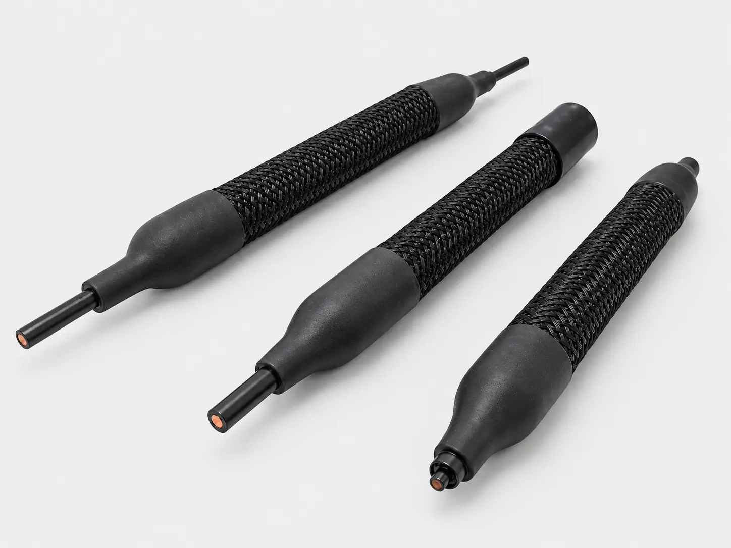
Best considered when: a cable-type anode assembly is designed for concentric or distributed installation.
Confirm: attenuation, active length, cable construction, seals, joints and reel handling.
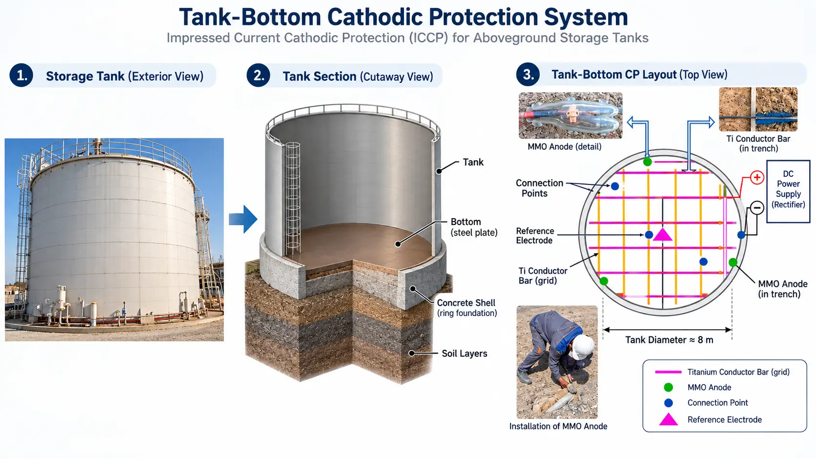
A new-build layout can be coordinated with the foundation before the bottom plate is installed. A replacement or double-bottom project may constrain anode height, routing, penetrations and test access. The issue-for-construction package should show each anode run, junction, reference electrode, monitoring lead and protected work sequence.
Tank diameter alone is not enough to determine layout or quantity. Foundation layers, liner, coating condition, current distribution and monitoring locations must also be reviewed.
Use these inputs to define the quotation and the approved anode supply schedule. The CP designer confirms the final design values.
| Decision | Why it matters | Evidence to provide |
|---|---|---|
| Tank geometry | Defines the protected footprint and distribution pattern. | Tank diameter, bottom arrangement, annular plates and layout drawing. |
| Foundation | Controls electrolyte path and installation method. | Sand pad, concrete, membrane/liner, resistivity and layer thicknesses. |
| Project type | New, replacement and double-bottom tanks have different access. | Construction sequence, available clearance and penetration details. |
| Current demand | Drives zones, anode length and power inputs. | CP calculation, coating basis, design current and design life. |
| Monitoring | Supports commissioning and long-term control. | Reference electrode type/location, test leads and data collection plan. |
| Connections | Field joints and continuity affect the distributed network. | Connection detail, welding method, cable schedule and inspection plan. |
Project review
The approved tank-bottom drawing should connect the anode pattern with the foundation build, cable routes and future monitoring points.
Coordinate anode runs, reference electrodes and cable exits before the bottom plates and foundation layers close access.
Check available height, penetrations, existing layers and the construction sequence before selecting a grid or ring geometry.
State current by zone, ribbon or linear run length, crossover method, feeding and isolation at the approved locations.
Identify continuity checks, as-built records, reference electrodes and test points that remain accessible after installation.
Define responsibilities in the purchase specification. HELE can configure and manufacture agreed anode components or assemblies; complete system engineering is not automatically included.
Inside HELE
HELE can verify supplied ribbon, mesh-ribbon, wire or linear elements against the agreed width, length, active zone, coating basis, factory leads and connection schedule. Prefabricated grids or sections need separate dimensional and continuity acceptance criteria.
Confirm the supplied titanium form, dimensions, active zone and order identification.
Control the specified coating basis, connection, cable, seal, backfill or mounting features included in the order.
Record continuity, connection or insulation results when the inspection plan defines method and acceptance limits.
Match drawings, inspection records, labels and packing documentation to the approved supply schedule.
Field installation, CP calculations, commissioning and performance acceptance follow the agreed project responsibility matrix.
Inquiry
Share the tank arrangement, foundation and current demand. A plan showing the bottom, liner and proposed anode runs will speed up the supply review.
Prefer email?
sales@heletitanium.comFactory & Engineering Center
Titanium Valley, Baoji City, Shaanxi Province, China