Buried Structures
Compare remote deep or shallow groundbeds with distributed linear layouts using soil resistivity, coating condition and interference risk.

ICCP Anode Layouts · Selection Overview
Compare remote groundbeds, distributed anodes, under-tank layouts, concrete installations and marine-mounted arrangements from the protected asset and its environment. HELE can configure the anode supply once the required current, installation interfaces and design basis are defined.
The responsible CP designer confirms final current demand, placement, interference review, protection criteria and commissioning method.
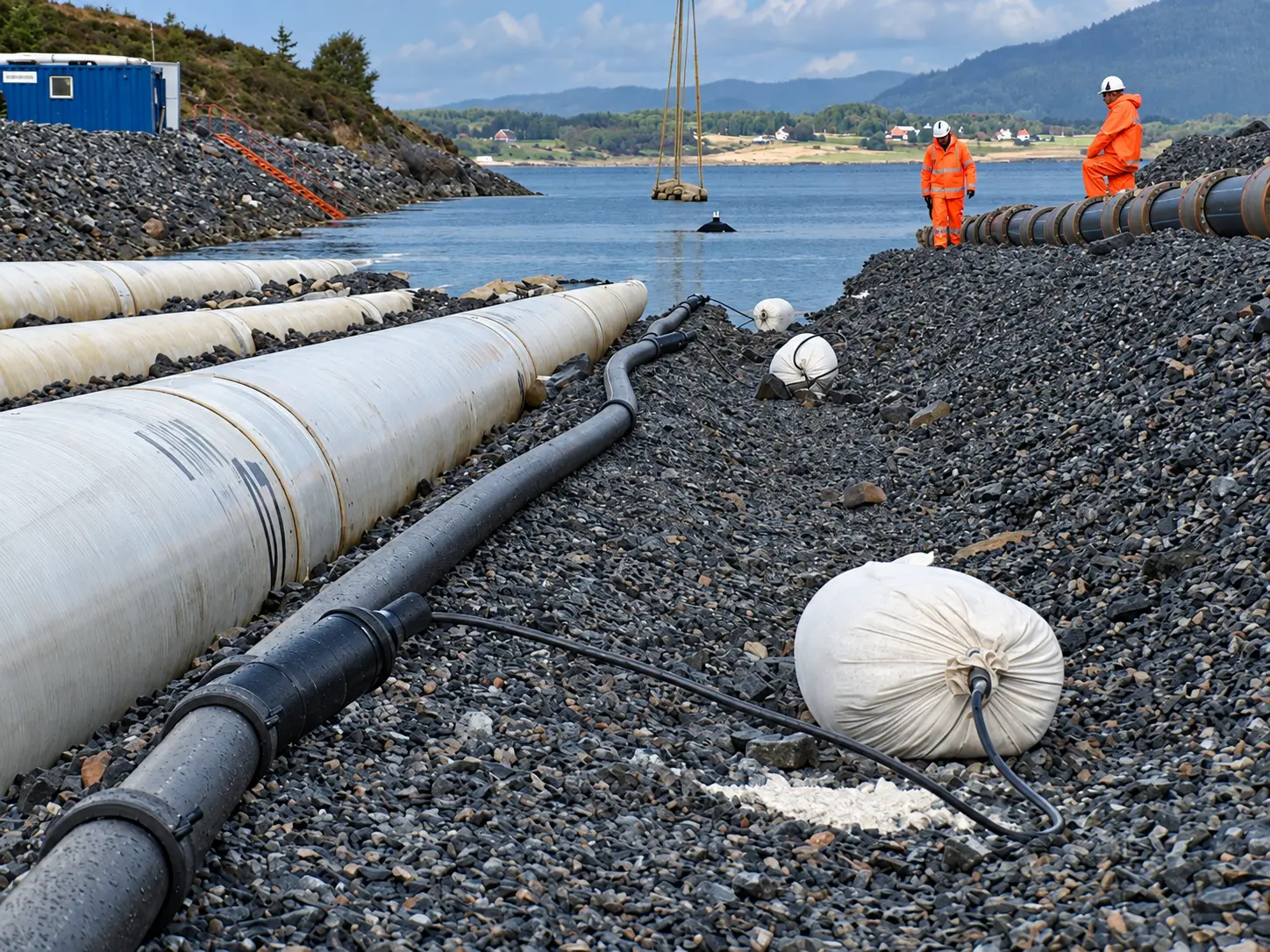
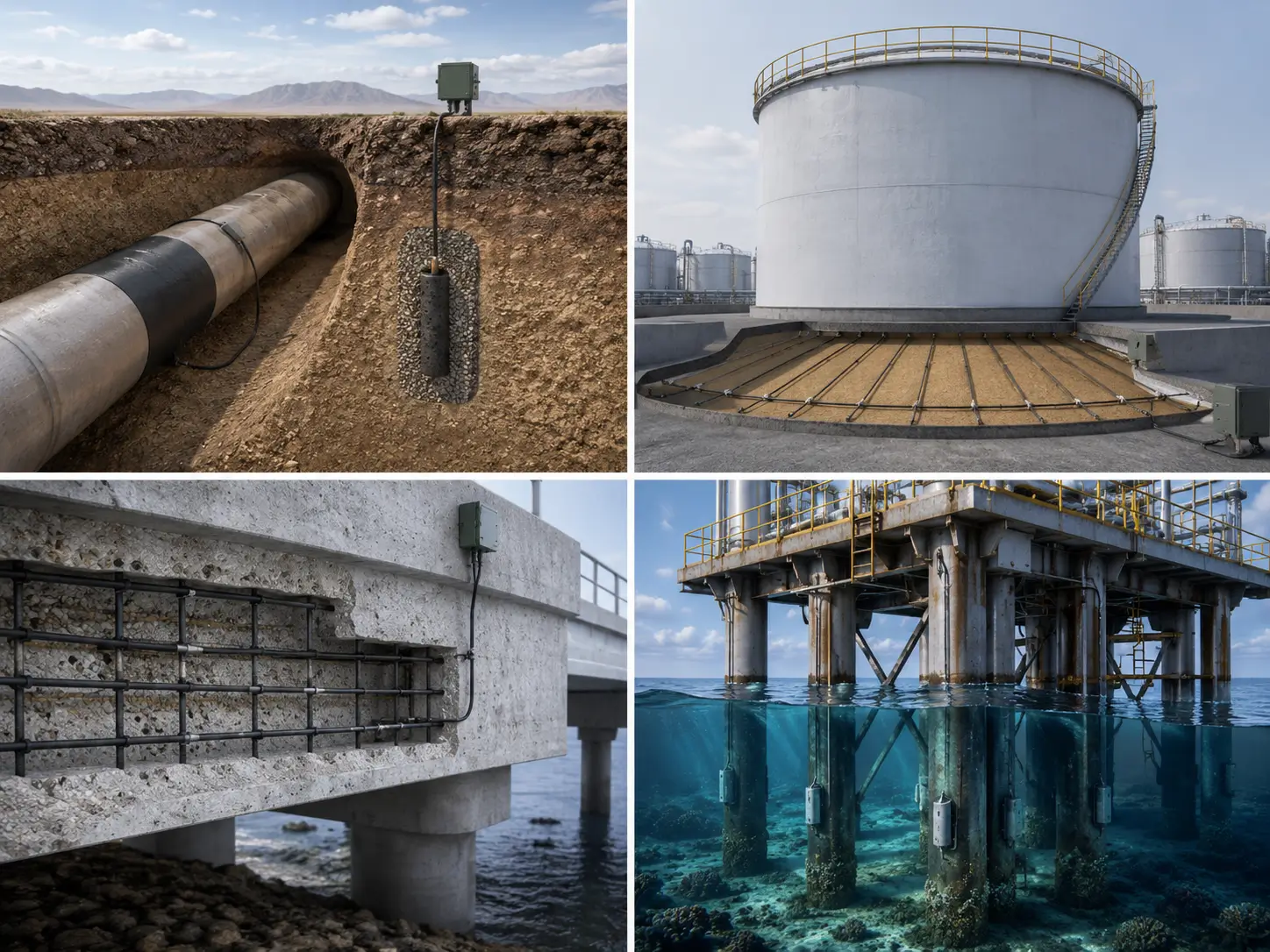
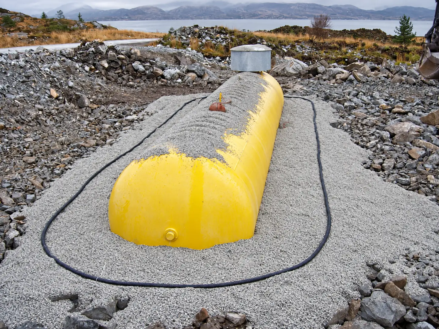
An ICCP layout is selected from the structure geometry, electrolyte, coating condition, current demand, access, cable routing, installation method and monitoring strategy. The same MMO coating can be packaged as a canister, tubular, linear, wire, ribbon, mesh ribbon, disc or rod assembly, but these forms are not interchangeable without design review.
Remote groundbeds concentrate anodes away from the protected structure, while distributed arrangements place anodes near the areas requiring current. Under-tank, concrete and marine systems add structure-specific constraints such as foundation layers, cover depth, seawater exposure, mounting protection and inspection access.
Start with the protected asset and installation environment, then compare current distribution, access and lifecycle requirements.
Compare remote deep or shallow groundbeds with distributed linear layouts using soil resistivity, coating condition and interference risk.
Evaluate grid, mesh-ribbon or concentric linear arrangements against tank foundation, liner, replacement-bottom and monitoring details.
Select mesh, ribbon, wire or discrete arrangements from concrete condition, reinforcement continuity, repair zones and overlay method.
Review tubular, disc or rod assemblies for seawater current distribution, shielding, cable protection and diver access.
These are configuration families, not pre-approved designs. The project specification determines dimensions, coating loading, cable, seals, backfill and assembly details.
Best considered when: the protected asset can be served from a separated deep or shallow groundbed.
Confirm: soil model, remote-earth behavior, borehole or trench details, backfill, venting and cable route.
Best considered when: current should be distributed along pipelines, tank perimeters or localized buried assets.
Confirm: routing, attenuation, spacing, joints, termination, backfill and interference review.
Best considered when: a low-profile distributed layout is needed under tanks or in concrete zones.
Confirm: grid geometry, crossing connections, substrate preparation, overlay or foundation interface.
Best considered when: anodes are mounted to jetties, offshore frames, seawalls or intake structures.
Confirm: mounting, dielectric shield, cable sealing, mechanical protection and inspection access.
A remote groundbed can simplify anode concentration and maintenance access, but its resistance, attenuation and interference effects depend on site conditions. A distributed arrangement can improve local current distribution, yet it creates more cable, splice and installation interfaces. Selection should be based on the complete CP model rather than anode shape alone.
Design control: Do not use a generic spacing, current-output or design-life value across different structures. Those values are project outputs, not fixed product specifications.
Use these inputs to define the quotation and the approved anode supply schedule. The CP designer confirms the final design values.
| Decision | Why it matters | Evidence to provide |
|---|---|---|
| Protected structure | Defines current distribution and mounting geometry. | Structure drawings, dimensions, coating data and electrical continuity. |
| Electrolyte | Soil, concrete and seawater require different installation interfaces. | Resistivity or conductivity, temperature, chemistry and seasonal variation. |
| Current demand | Drives anode quantity, loading, cable and power-system inputs. | Design current, zones, design life and governing calculation. |
| Access & Constructability | Controls groundbed, trench, embedding, mounting and replacement strategy. | Site plan, work method, lifting/access limits and installation sequence. |
| Monitoring | Reference electrodes and test points support control and verification. | Monitoring philosophy, locations, cable schedule and acceptance plan. |
Project review
The anode form follows the approved CP layout. These four checks prevent a quotation for an electrode alone from being compared with a complete installable assembly.
Confirm the protected zones, coating condition, electrolyte and distribution model before fixing anode spacing or number.
Show boreholes, trenches, tank foundations, concrete cover or marine mounting points on the issued layout.
Define leads, junctions, reference electrodes, cable protection, power supply and field termination responsibilities.
Agree the shop inspection, installation checks and commissioning records that belong to each supplier or contractor.
Define responsibilities in the purchase specification. HELE can configure and manufacture agreed anode components or assemblies; complete system engineering is not automatically included.
Inside HELE
For each ordered anode form, HELE can align material identity, active zone, cable or conductor details, sealing, dimensions and labels with the approved schedule. The required inspection records and acceptance methods should be agreed before manufacture.
Confirm the supplied titanium form, dimensions, active zone and order identification.
Control the specified coating basis, connection, cable, seal, backfill or mounting features included in the order.
Record continuity, connection or insulation results when the inspection plan defines method and acceptance limits.
Match drawings, inspection records, labels and packing documentation to the approved supply schedule.
Field installation, CP calculations, commissioning and performance acceptance follow the agreed project responsibility matrix.
Inquiry
Send the asset drawing and available CP design inputs. HELE can review the anode form, assembly interfaces and document package that fit the specified layout.
Prefer email?
sales@heletitanium.comFactory & Engineering Center
Titanium Valley, Baoji City, Shaanxi Province, China