ICCP Anodes for Tank Bottom Protection
Custom MMO ribbon, mesh ribbon, wire, and linear anode solutions for storage tank bottom cathodic protection, under-tank ICCP layouts, tank farms, above-ground storage tanks, and distributed current output systems.
Tank Bottom ICCP Engineering
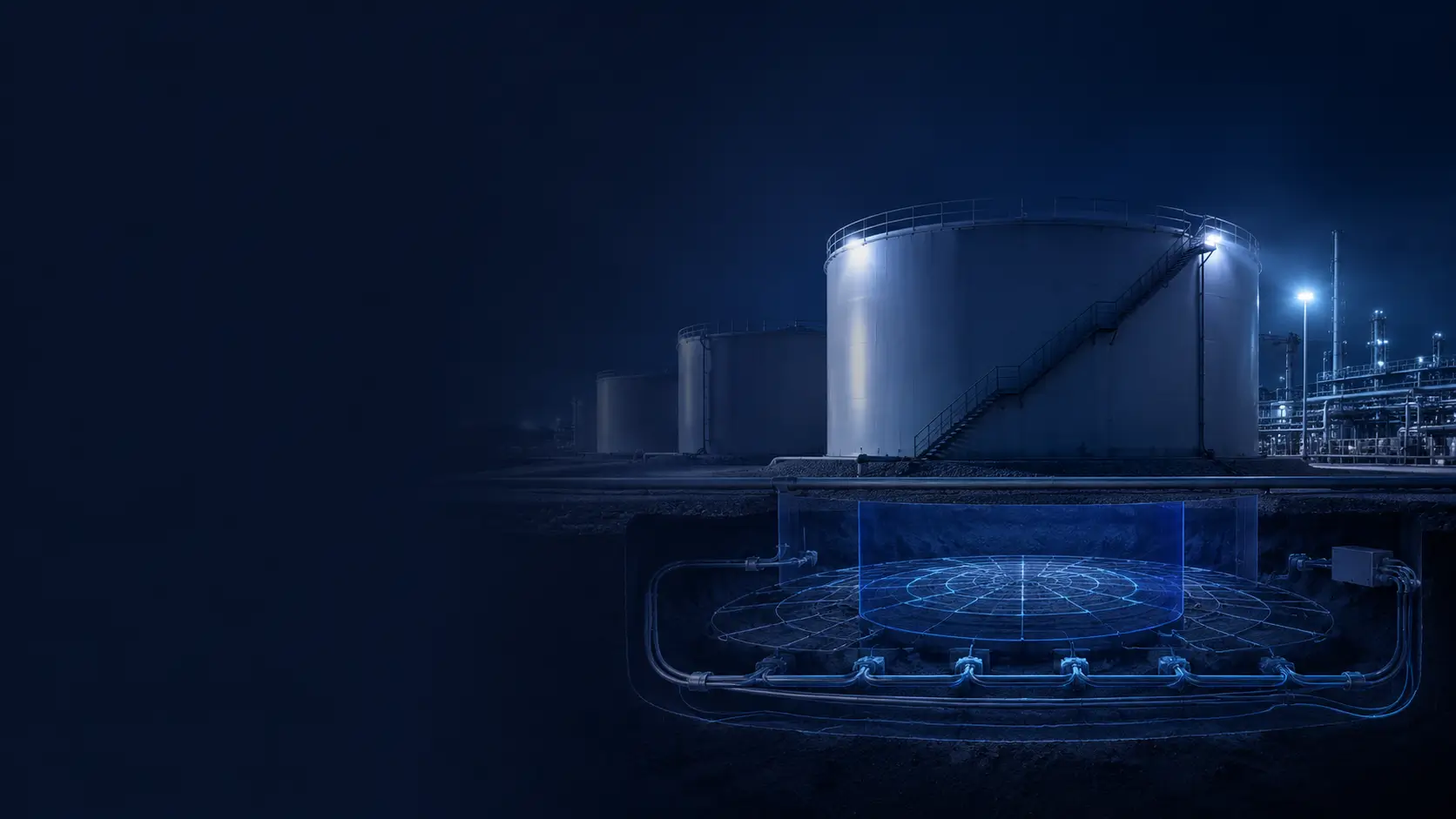
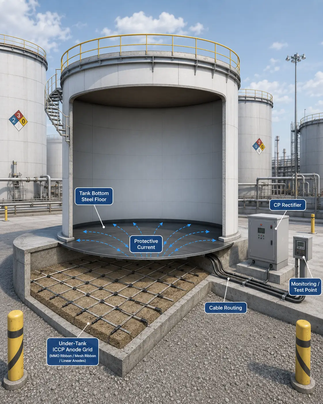
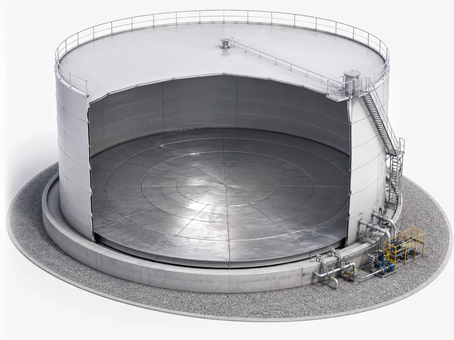
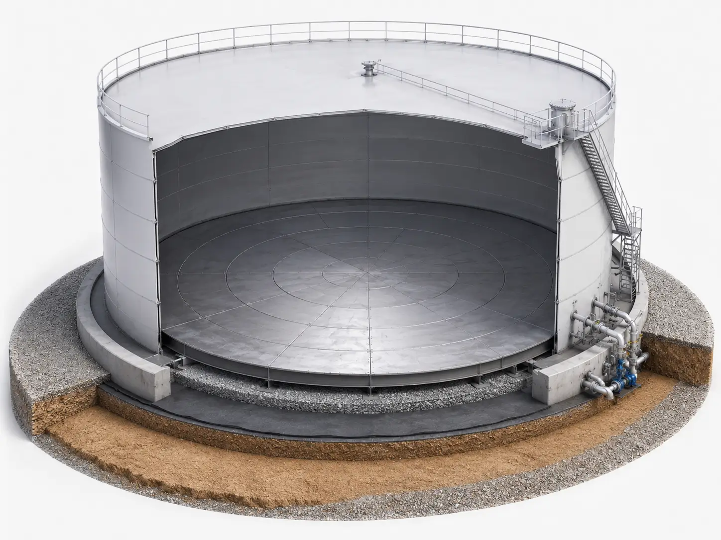
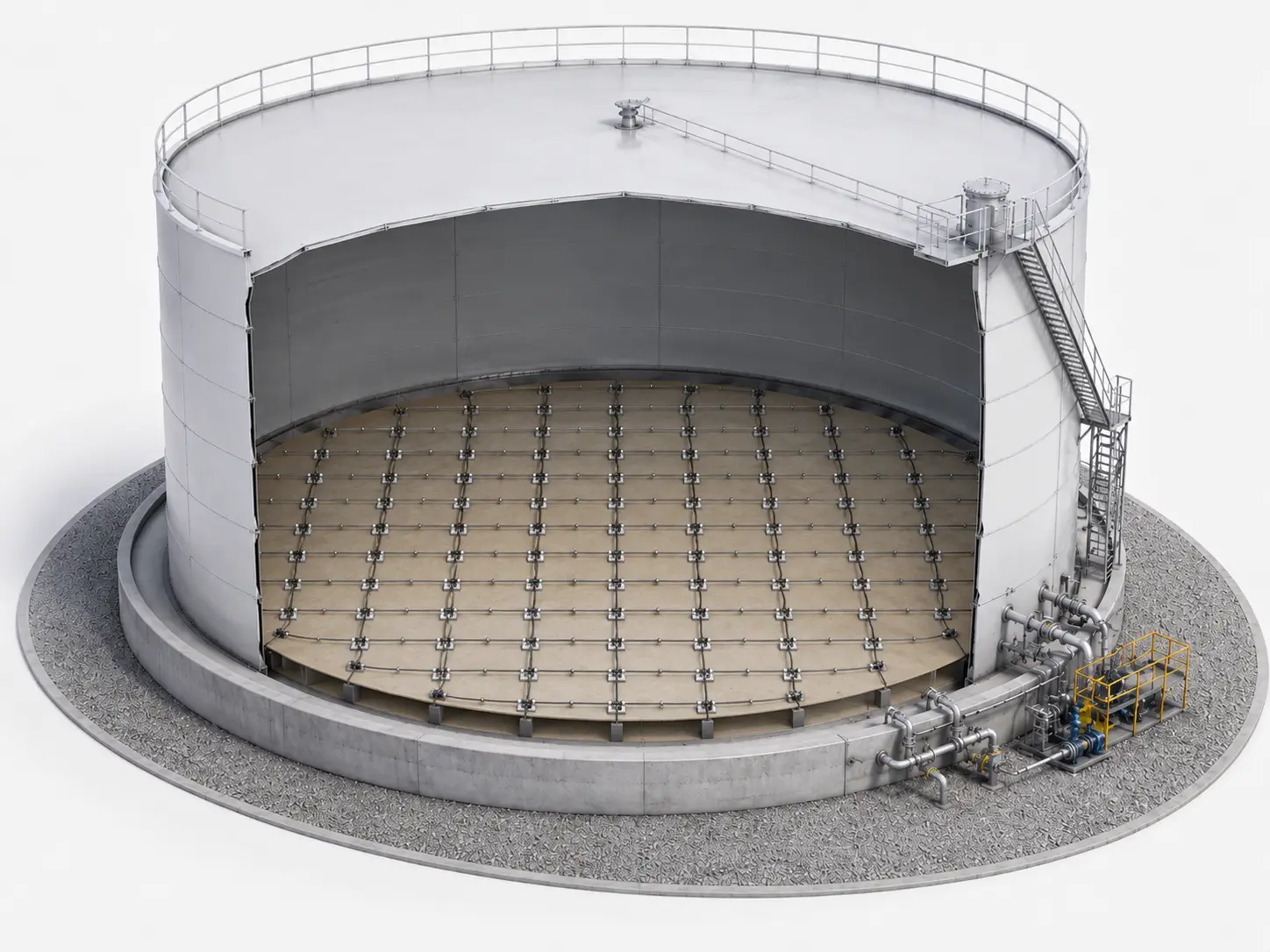
Tank Bottom Protection Requires Distributed Current Output
Tank bottom ICCP systems are used to help protect above-ground storage tank floors from soil-side corrosion. Because the tank bottom is a large, flat structure, the anode layout should be designed to distribute protective current across the protected area as evenly as practical.
Unlike point-type groundbed systems, under-tank ICCP layouts usually require distributed anode forms placed beneath or around the tank bottom. The final anode form, spacing, cable routing, reference electrode location, and current output should be reviewed according to tank diameter, foundation type, soil or sand resistivity, coating condition, current demand, and design life target.
Hele Titanium supports MMO ribbon anodes, MMO mesh ribbon anodes, MMO wire anodes, and MMO linear anodes for tank bottom ICCP systems, with coating review, current output review, cable connection, labels, packing, and documentation support according to project requirements.
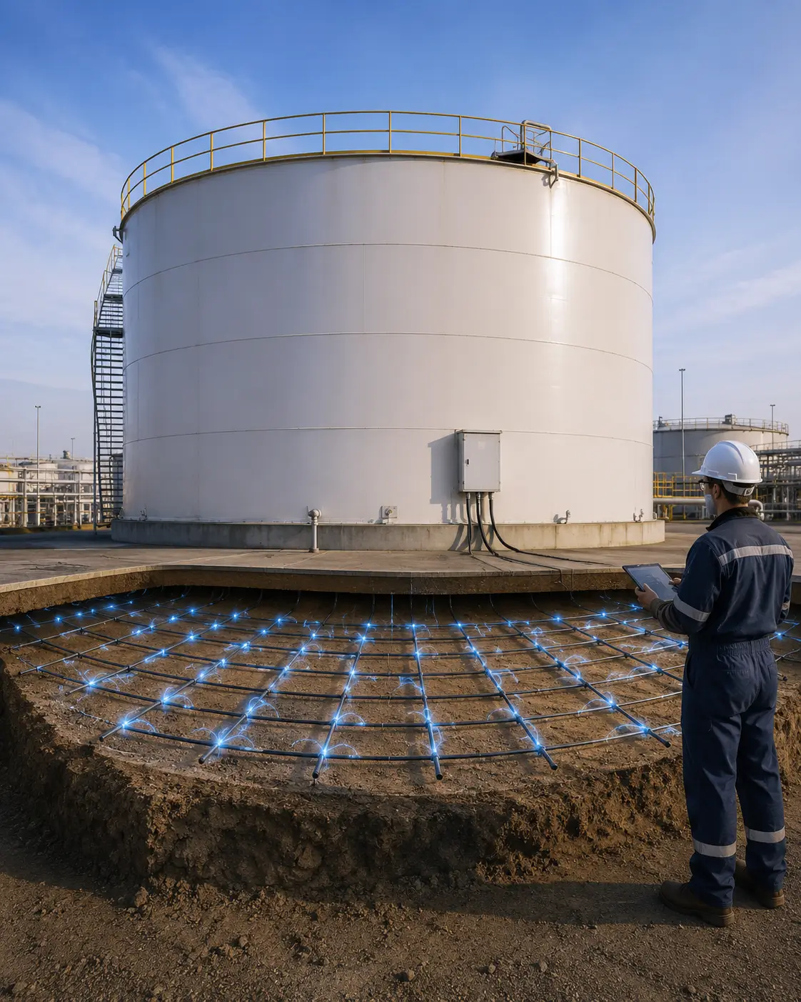
Under-Tank Distributed Layout
Anode forms can be reviewed for distributed current output beneath or around storage tank bottoms.
MMO Linear Anode Form Matching
Ribbon, mesh ribbon, wire, and linear anodes can be matched to the tank layout and current distribution needs.
Tank Diameter & Current Review
Tank size, current demand, anode spacing, and design life target should be reviewed together.
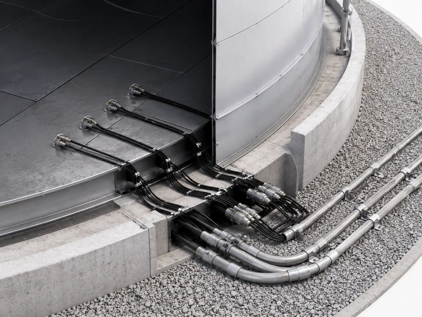
Cable, Monitoring & Documentation
Cable routing, connection, labels, reference electrode coordination, packing, MTC, and coating records can be supported.
What Is Tank Bottom ICCP Protection?
Tank bottom ICCP protection is an impressed current cathodic protection method used to help protect the underside of above-ground storage tank floors from corrosion. In many tank farm projects, anodes are installed beneath the tank bottom, within the foundation system, or around the tank area to deliver protective current to the steel floor.
Answer
Because storage tank bottoms are large and flat, distributed anode layouts are often reviewed. MMO ribbon, mesh ribbon, wire, or linear anodes can be used depending on tank diameter, foundation design, resistivity, installation access, current demand, and project specification.
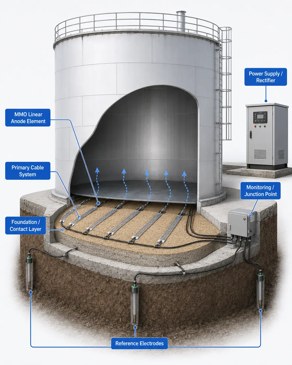
1. Tank Bottom Steel Floor
What It Does: The protected structure that needs soil-side corrosion control.
Why It Matters: Tank diameter, floor condition, and coating condition affect current demand.
2. Under-Tank Anode Layout
What It Does: Places anodes beneath or around the tank bottom for distributed current output.
Why It Matters: Layout affects current distribution and protection coverage.
3. MMO Linear Anode Forms
What It Does: Ribbon, mesh ribbon, wire, or linear anodes provide distributed current output.
Why It Matters: Different anode forms fit different foundation and installation methods.
4. Cable Routing
What It Does: Connects anodes to the power source and test / junction points.
Why It Matters: Cable route and protection affect long-term system reliability.
5. Reference Electrodes & Monitoring Points
What It Does: Support potential measurement and system commissioning.
Why It Matters: Monitoring layout helps verify and adjust system operation.
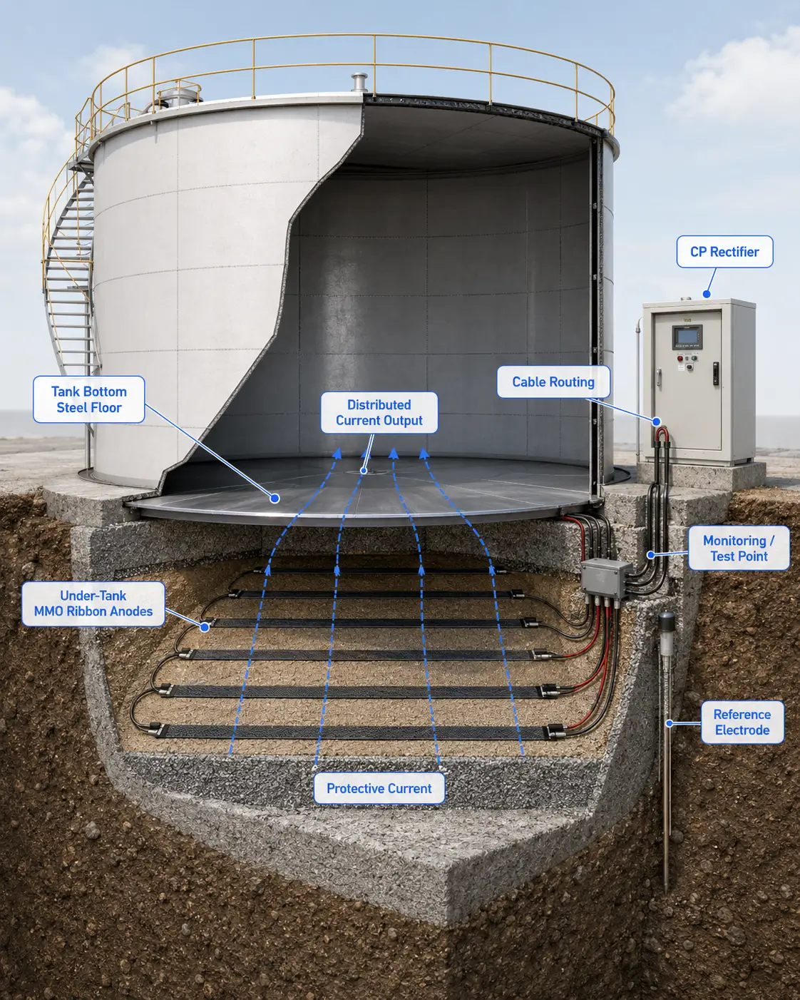
Tank bottom ICCP provides distributed current output to protect the underside of above-ground storage tanks.
Recommended MMO Anode Forms for Tank Bottom ICCP Systems
Tank bottom ICCP systems can use different MMO linear anode forms depending on tank diameter, foundation design, current demand, anode spacing, cable route, and installation method. The final recommendation should be based on CP design data and site conditions.
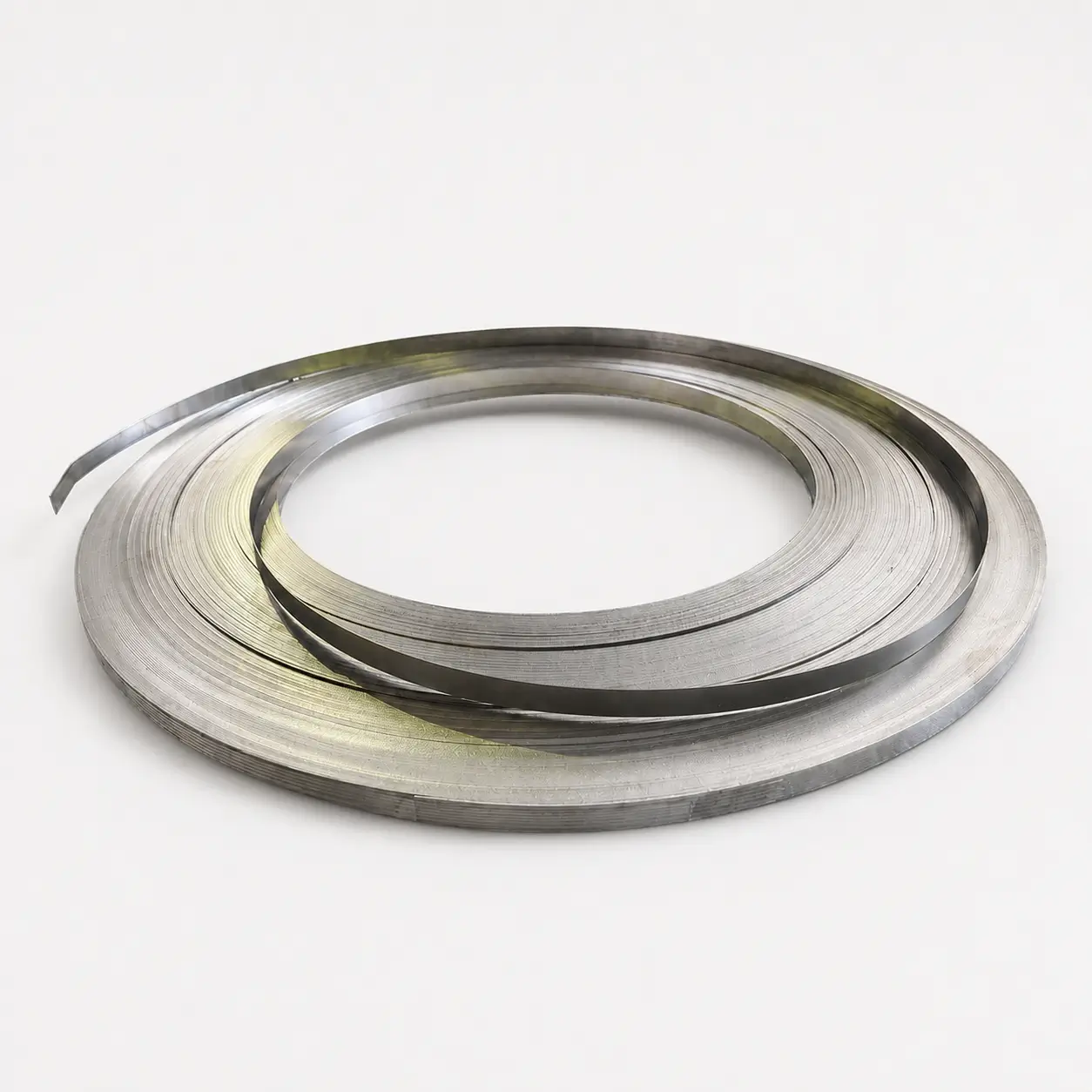
MMO Ribbon Anodes
Flat MMO coated titanium ribbon anodes for under-tank distributed current output and long-area CP layouts.
Best For:
Storage tank bottom protection, under-tank anode grids, tank farms, and flat distributed current layouts.
Key Review Factors:
Ribbon width, coated length, current output, anode spacing, soil or sand resistivity, cable connection, and foundation type.
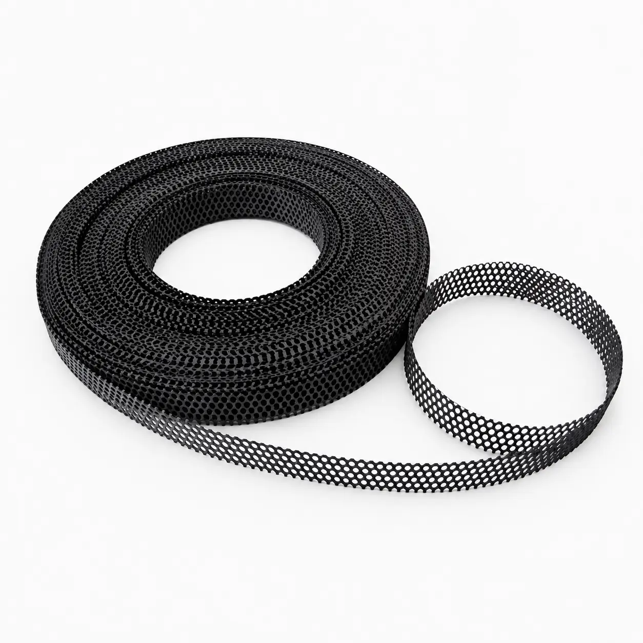
MMO Mesh Ribbon Anodes
Open mesh MMO coated titanium ribbon anodes for larger contact area and distributed current output.
Best For:
Tank bottom CP layouts requiring open mesh contact, embedded placement, or large-area current distribution.
Key Review Factors:
Mesh opening, ribbon width, coated length, backfill or sand contact, current output, and installation method.
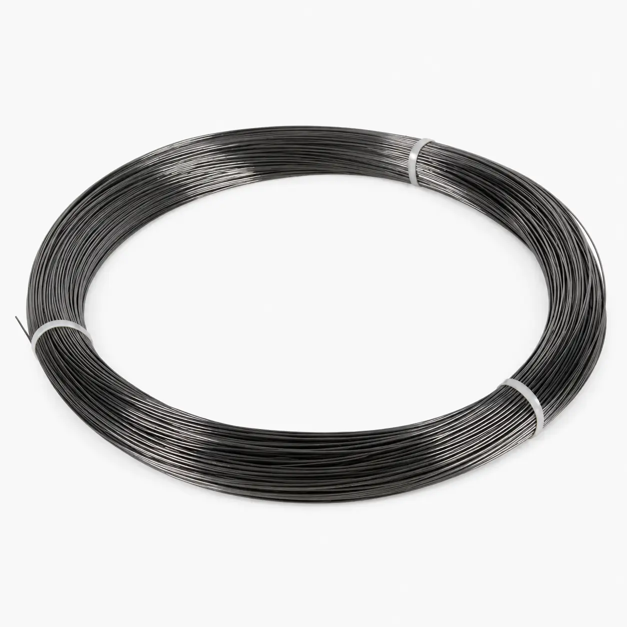
MMO Wire Anodes
Flexible MMO coated titanium wire anodes for routed, embedded, or compact distributed tank bottom layouts.
Best For:
Projects requiring flexible routing, narrow installation paths, or defined anode spacing.
Key Review Factors:
Wire diameter, coated length, route design, spacing, current output, and cable connection.
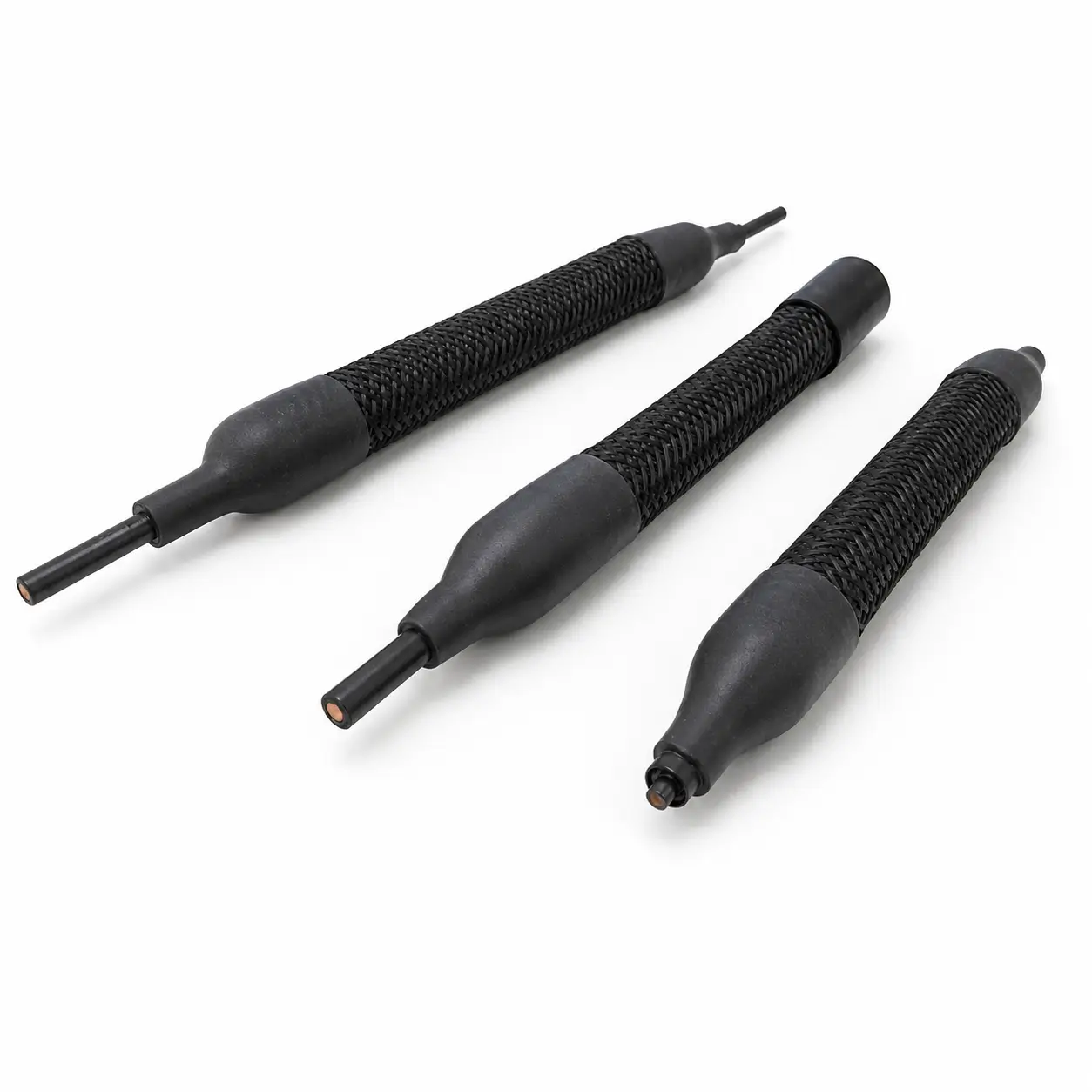
MMO Linear Anode Systems
Continuous or semi-continuous MMO linear anode layouts designed for distributed current output across tank bottom protection zones.
Best For:
Large tank bottoms, distributed CP grids, long-area protection, and custom under-tank layouts.
Key Review Factors:
Tank diameter, total current demand, output per meter, spacing, cable route, and design life.
Where Tank Bottom ICCP Anodes Are Commonly Used
Tank bottom ICCP anode systems are commonly reviewed for above-ground storage tanks, tank farms, and industrial facilities where the underside of steel tank floors requires corrosion protection. The final anode layout should be reviewed according to tank geometry, foundation conditions, current demand, monitoring requirements, and installation access.
| Application | Why Tank Bottom ICCP May Fit | Key Review Factors |
|---|---|---|
|
|
Distributed anode layouts can help deliver protective current to the underside of tank floors. | Tank diameter, floor condition, coating condition, foundation type, resistivity, and current demand. |
|
|
Multiple tanks may require coordinated anode layouts, cable routing, and monitoring points. | Tank spacing, electrical interference, CP zones, cable routes, junction boxes, and documentation. |
|
|
Tank bottom protection may be reviewed where soil-side corrosion risk affects long-term tank integrity. | Chemical facility layout, foundation material, current demand, monitoring plan, and safety requirements. |
|
|
Under-tank anode systems can be designed before the tank floor or foundation is completed. | Foundation drawing, tank diameter, sand or concrete base, anode grid layout, and cable exit points. |
|
|
Retrofit protection may be reviewed when existing tank conditions and installation access allow CP upgrade. | Existing foundation, access limitations, current demand, reference electrode placement, and installation constraints. |
|
|
Distributed ICCP layouts can support tank bottom protection across large storage facilities. | Tank group layout, power supply location, cable routing, monitoring points, current distribution, and project standard. |
Not sure whether tank bottom ICCP is suitable for your project?
Share your tank geometry, foundation conditions, required current output, available layout and cable route for engineering review.
Key Design Parameters for Tank Bottom Anode Selection
A reliable tank bottom ICCP anode recommendation requires project data. The anode form, spacing, cable route, current output, monitoring plan, and documentation should be reviewed based on the full tank bottom CP design.
Tank Diameter & Floor Area
- Tank size and floor area dimensions
- Affects current demand and anode layout
- Determines spacing and total anode quantity
Foundation Type
- Sand pad, concrete ring wall, or liner system
- Double bottom or special foundation design
- Directly affects the installation method
Soil / Sand Resistivity
- Resistivity below or around the tank
- Affects current distribution and flow
- Critical for proper anode selection
Current Demand
- Total current and current density
- Output per meter and operating profile
- Affects coating loading and anode spacing
Anode Layout & Spacing
- Ribbon, mesh ribbon, wire, or linear anode
- Spacing should match protection area
- Ensures complete tank bottom coverage
Cable Route & Exit Points
- Cable routing and physical protection
- Junction points and exit locations
- Must be planned before installation
Reference Electrode / Monitoring Plan
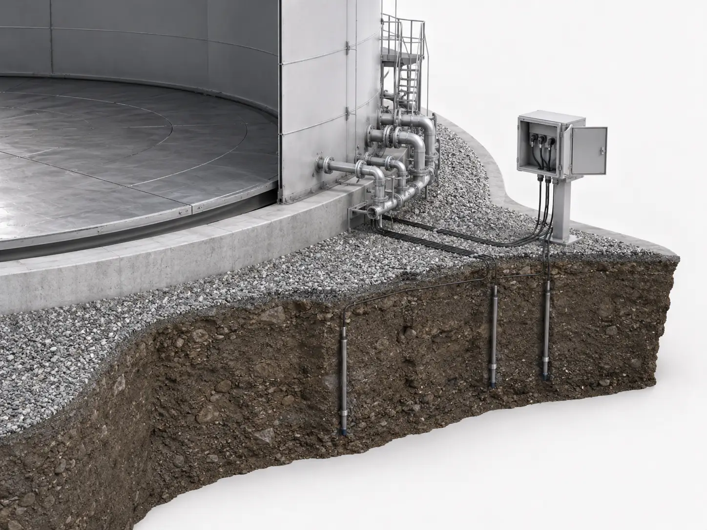
- Reference electrode location and test points
- Monitoring access and system integration
- Reviewed during layout design phase
Documentation Requirements

- MTC, coating records, and dimensional inspection
- Cable records, labels, and packing list
- Project documents prepared when required
Share Your Project Data for Engineering Review
Provide tank dimensions, foundation type, sand resistivity, required current output, and monitoring requirements for accurate tank bottom anode design.
Complete Under-Tank ICCP Anode System Components to Review
An under-tank ICCP system is more than the anode itself. Review the complete under-tank layout, MMO anode system, cable routing, foundation contact, reference electrodes, power supply, monitoring points and documentation together to support reliable tank bottom cathodic protection, commissioning and long-term operation.
| Component | Function in the System | What to Confirm |
|---|---|---|
|
|
Provides distributed current output beneath the tank bottom through durable coated titanium anode. | Ribbon, mesh ribbon, wire or linear anode form, coated length, output per meter, spacing and expected life. |
|
|
Transports current from the rectifier or junction point to the under-tank anode layout. | Cable size, insulation rating, length, exit points, routing protection, sealing and labeling. |
|
|
Provides the contact environment between the anode system and the tank bottom protection zone. | Sand, soil, backfill, concrete, liner condition, moisture level and current transfer path. |
|
|
Support commissioning, monitoring and future potential measurement of the tank bottom CP system. | Electrode type, quantity, location, cable route, accessibility and monitoring plan. |
|
|
Delivers controlled DC output to the under-tank impressed current cathodic protection system. | Output voltage, current capacity, control mode, total current demand and system resistance. |
|
|
Provide connection, identification and testing access for anode cables, reference electrodes and monitoring circuits. | Box rating, cable termination, identification, test access, protection and maintenance access. |
|
|
Protects cable penetrations and connection areas from moisture ingress and mechanical damage. | Sealing method, cable exit location, protection sleeve, strain relief and installation sequence. |
|
|
Provides records for installation, commissioning, monitoring and future maintenance. | Layout drawings, data sheets, cable records, reference electrode records, test results and O&M documents. |
Buyer Note: Under-tank ICCP system review should consider both the physical components and the tank foundation environment. Share your tank drawing, foundation details, soil or sand condition, current demand, anode layout, cable routing, reference electrode plan and documentation requirements for engineering review.
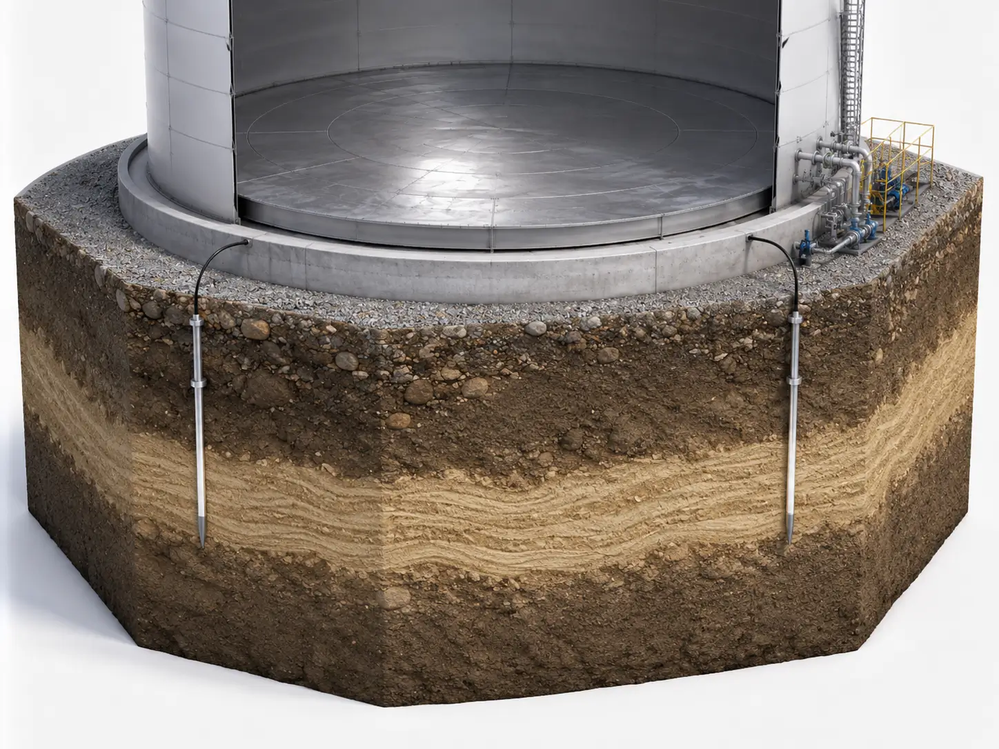
Current Distribution, Anode Spacing and Foundation Conditions Must Be Reviewed Together
For tank bottom ICCP systems, anode selection cannot be based only on ribbon width or wire diameter. Tank size, foundation conditions, resistivity, anode spacing, cable routing, reference electrode position, current output, and design life all affect the final recommendation.
1 Tank Diameter & Protection Area
Larger tank floors may require more distributed anode layouts and careful spacing review.
2 Foundation Contact
Sand, soil, concrete, liner, or backfill conditions affect current transfer beneath the tank.
3 Output per Meter
Current output per meter should be reviewed according to CP design, coating loading, spacing, and design life.
4 Cable & Monitoring Layout
Cable routes, junction points, reference electrode positions, and access points should be planned early.
* All recommendations are reviewed according to project requirements and based on operating conditions.
Tank Bottom ICCP Installation Risk Factors to Review
Many tank bottom CP issues are related not only to anode material, but also to foundation conditions, poor cable routing, incomplete current demand data, incorrect spacing, or limited monitoring access. Reviewing these issues before production helps improve anode selection and project planning.
Missing Tank Foundation Data
Without foundation details, anode placement and current transfer assumptions may be less reliable.
Incorrect Anode Spacing
Poor spacing can lead to uneven current distribution beneath the tank floor.
Poor Cable Route Planning
Cable exit points, protection, and junction locations should be confirmed before installation.
Limited Reference Electrode Access
Reference electrode placement affects commissioning, monitoring, and long-term CP system review.
Foundation or Liner Constraints
Double bottoms, liners, sand pads, or concrete base designs may affect installation options.
Incomplete Current Demand Review
Current requirement should be reviewed based on tank size, coating condition, environment, and design life.
Buyer Note:
If your project already has a tank drawing, foundation drawing, CP design calculation, current demand estimate, or resistivity report, share it with Hele Titanium for anode form and documentation review.
Quality & Documentation Support for Tank Bottom ICCP Anode Projects
Tank bottom ICCP anode project quality depends on MMO coating control, coated length accuracy, current output design, cable connection, label identification, packing protection, and final documentation.
Available Documents May Include:
- MTC
- Coating record
- Coated length record when required
- Dimensional inspection record
- Cable / connection inspection notes when required
- Visual inspection notes
- Packing list & Product labels
- Project-specific QC documents
- Third-party inspection support when required
1. MMO Anode Form Review
MMO ribbon, mesh ribbon, wire, or linear anode forms are reviewed according to substrate, size, coating, and output requirements.
2. Coating Control
Coating formulation, application cycles, drying, thermal treatment, and coating loading are controlled according to project requirements.
3. Coated Length & Dimension Check
Ribbon width, mesh opening, wire diameter, coated length, total length, and connection details are reviewed according to agreed scope.
4. Cable & Connection Review
Cable length, insulation, connection method, sealing, labels, and termination details can be reviewed when required.
5. Packing & Labeling
Anodes are packed according to product form, cable protection, coating sensitivity, destination, and shipment requirement.
6. Project Documentation
Documentation and inspection notes can be prepared based on agreed inspection scope.
Explore More ICCP Anode Applications
If your project is not a tank bottom protection system, explore other ICCP anode application pages to compare suitable installation methods and anode forms.
ICCP Anode Installation Configurations
A complete overview of deep groundbed, shallow groundbed, tank bottom, concrete, marine, distributed, and localized ICCP layouts.
View Installation Configurations →ICCP Anodes for Deep Groundbed Systems
For deep well and shallow groundbed systems using canister, tubular, or rod MMO anodes.
View Deep Groundbed ICCP Anodes →ICCP Anodes for Reinforced Concrete Protection
For bridges, piers, decks, and chloride-contaminated concrete using wire, mesh ribbon, ribbon, or disc anodes.
View Concrete ICCP Anodes →ICCP Anodes for Marine Structures
For jetties, piers, harbors, seawalls, offshore structures, and water intake systems using tubular, disc, or rod anodes.
View Marine ICCP Anodes →ICCP Anodes for Pipelines & Buried Structures
For buried pipelines, underground tanks, and buried steel structures using canister, tubular, or linear anode systems.
View Pipeline & Buried Structure ICCP Anodes →Tank Bottom ICCP Anode FAQ
What is tank bottom ICCP protection?
What anode forms are used for tank bottom protection?
Why are ribbon and mesh ribbon anodes commonly reviewed for under-tank layouts?
What is the difference between MMO ribbon, mesh ribbon, and wire anodes for tank bottom CP?
What information is needed for a tank bottom anode quote?
Why is tank diameter important for tank bottom CP design?
Why is soil or sand resistivity important?
How does anode spacing affect current distribution?
Can cable length and connection be customized?
Can reference electrode layout be considered with the anode system?
What documents can be provided?
Can Hele Titanium support new tank and retrofit tank bottom CP projects?
Get Your Tank Bottom ICCP Anode Recommendation
Tell us your tank diameter, foundation design, soil or sand resistivity, current demand, design life target, preferred anode layout, cable routing, reference electrode requirements, and documentation needs. Hele Titanium will help review suitable MMO anode forms and tank bottom ICCP configurations for your project.
-
MMO Ribbon, Mesh Ribbon, Wire and Linear Anode Support
Matched to your foundation and current needs.
-
Under-Tank Current Distribution and Spacing Review
Based on tank diameter and CP design data.
-
Cable Connection, Labels and Documentation Support
MTC and inspection records prepared when required.
-
Factory-Direct MMO Anode Manufacturing and Export Packing
Controlled quality from substrate to shipment.