Electrochemical Duty
Hydrogen output, active area, cell count, current density basis, voltage, power and operating profile.

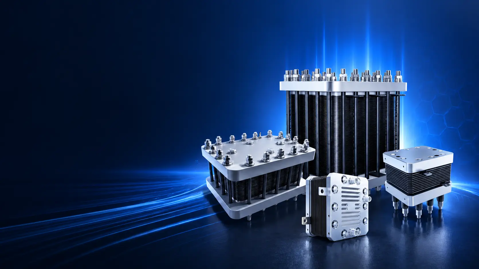
Water Electrolysis · OEM Stack Modules · Drawing-Based Integration
PEM electrolyzer stack modules reviewed against active area and cell count, current/voltage and hydrogen duty, pressure differential, water and thermal conditions, manifolds, sealing/compression, electrical/fluid interfaces and acceptance testing.
Product identity: this page concerns PEM water-electrolysis stacks—not PEM fuel-cell stacks. System-level purity, dew point, pressure delivery, specific energy and safety compliance cannot be assigned to the bare stack without its balance of plant and test boundary.
The stack must be matched to the electrochemical duty and the OEM system that feeds, powers, cools, controls and protects it. Envelope dimensions alone cannot define a replacement or new stack.
Hydrogen output, active area, cell count, current density basis, voltage, power and operating profile.
Water quality/flow, inlet temperature, heat rejection, cooling interface, contaminants and monitoring.
Hydrogen/oxygen pressures, differential pressure, transients, manifolds, seals, crossover and test boundary.
Electrical terminals, fluid ports, supports, sensors, insulation, compression, controls and service access.
Use the published output to identify a practical stack-family starting point, then freeze the electrical, water, thermal, pressure, interface and test basis for the ordered configuration. A stack output value does not by itself define complete-system hydrogen delivery.
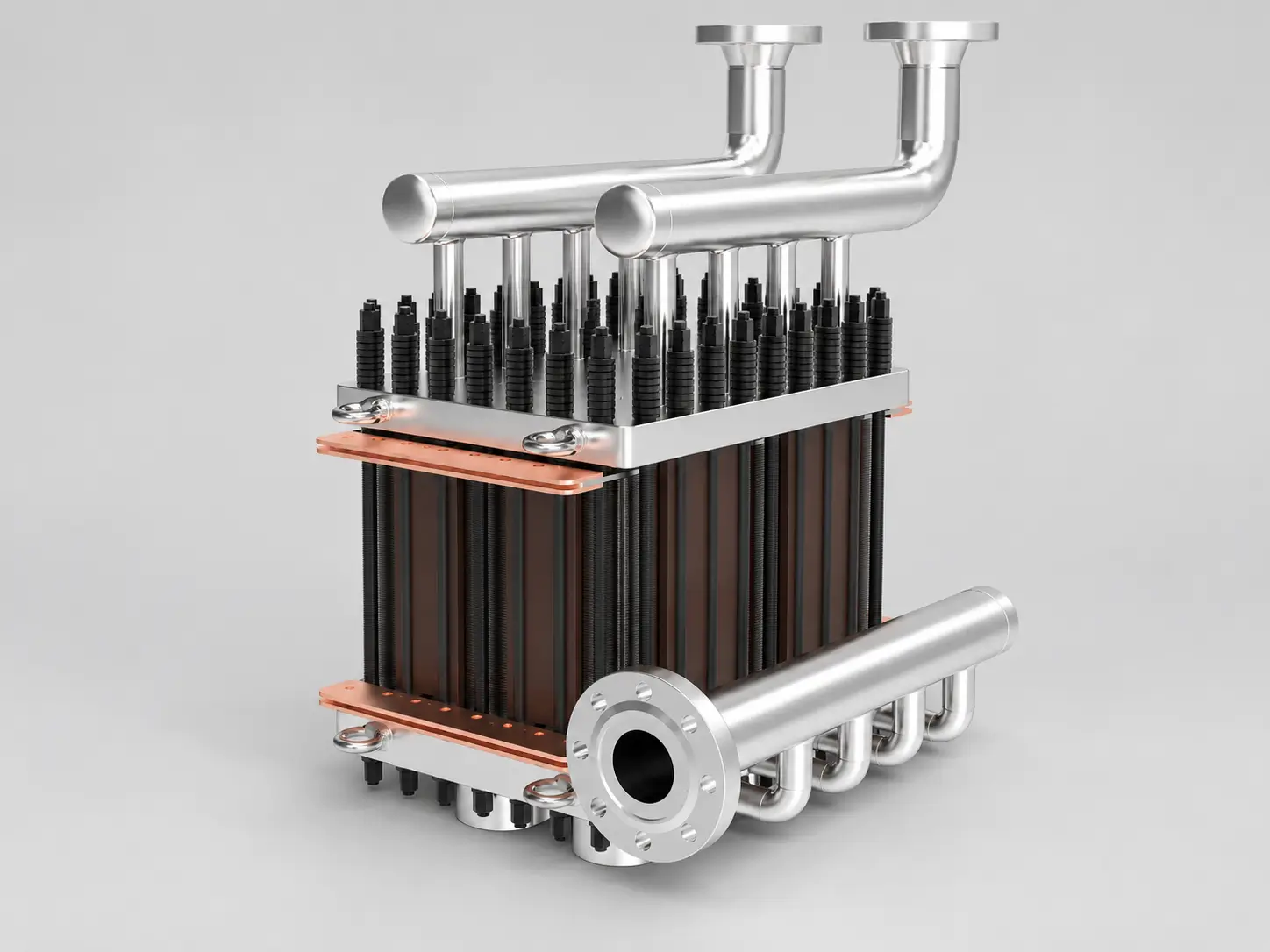
01 · Stack family
Reference Stack Hydrogen Output
50–300 Nm³/h H₂
Large stack direction requiring frozen active area and cell count, current and voltage, manifolds, compression, pressure, thermal management and test basis.
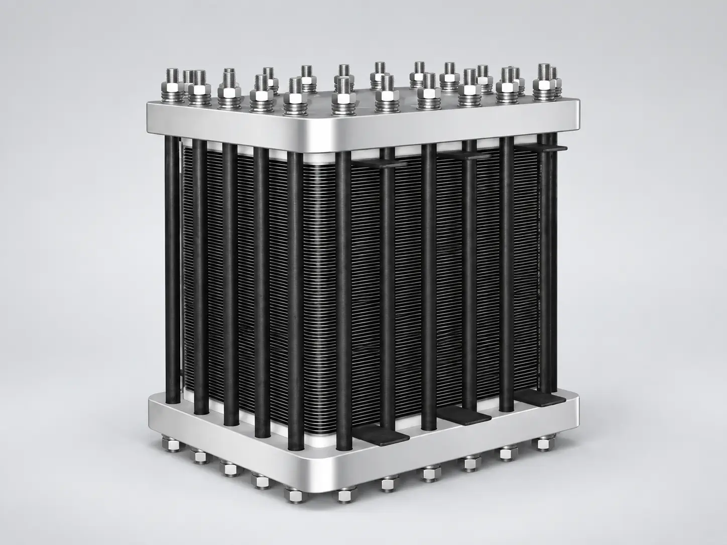
02 · Stack family
Reference Stack Hydrogen Output
1–10 Nm³/h H₂
OEM stack family reviewed against hydrogen duty, electrical window, envelope, water, pressure and balance-of-plant interfaces.
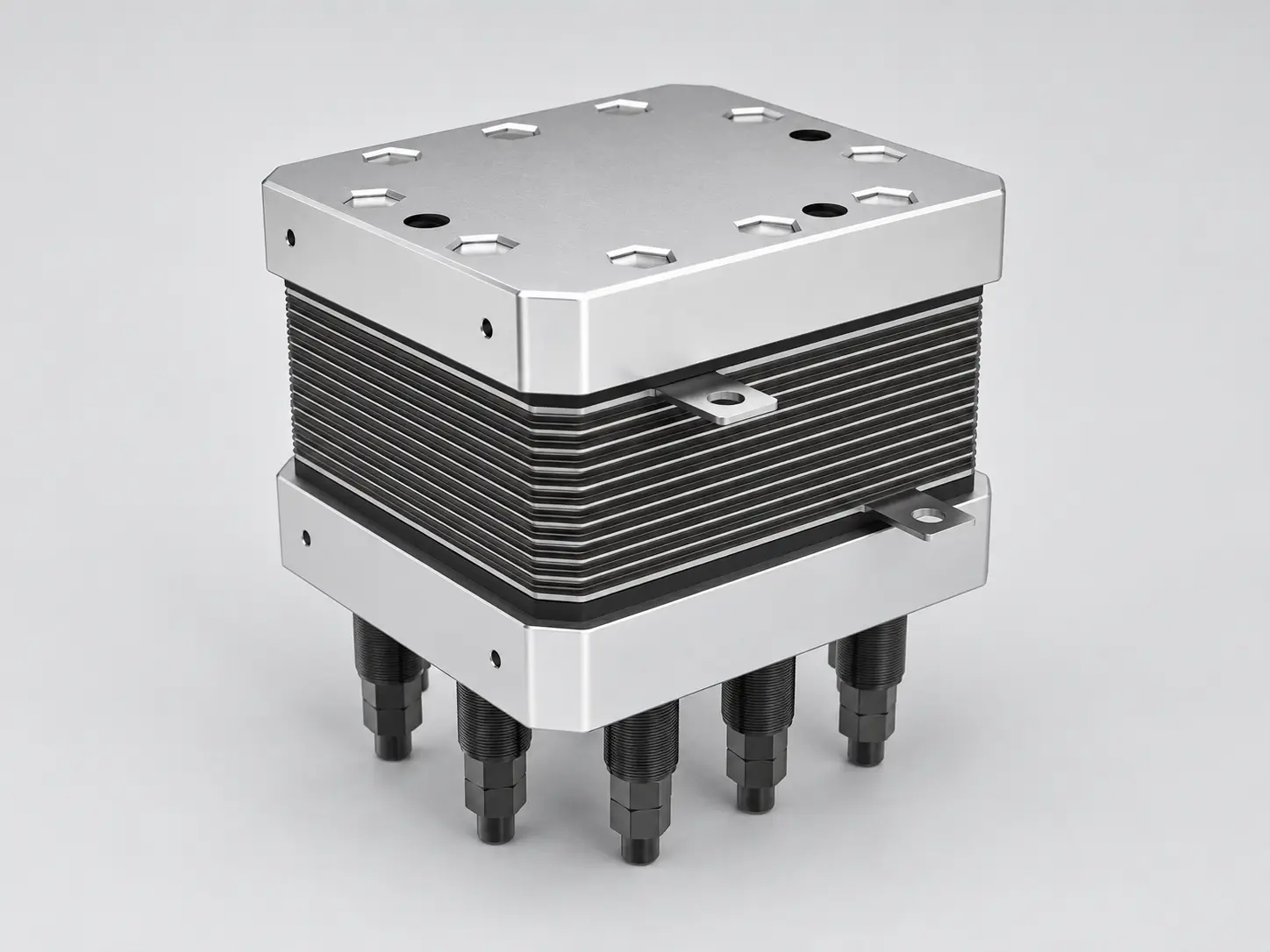
03 · Stack family
Reference Stack Hydrogen Output
0.6 Nm³/h H₂
Compact module for space-constrained or modular systems with defined current feed, fluids, cooling, support and service access.
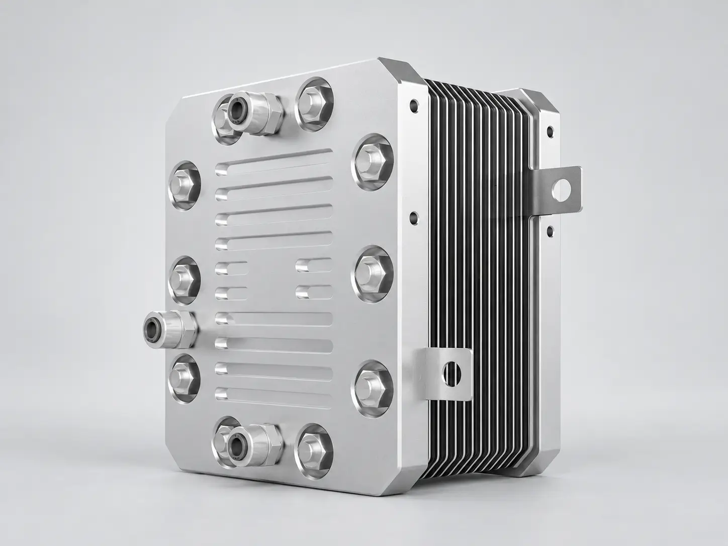
04 · Stack family
Reference Stack Hydrogen Output
3200–5000 mL/min H₂
Higher-output compact stack direction whose operating point, pressure, temperature and acceptance test require order-specific definition.
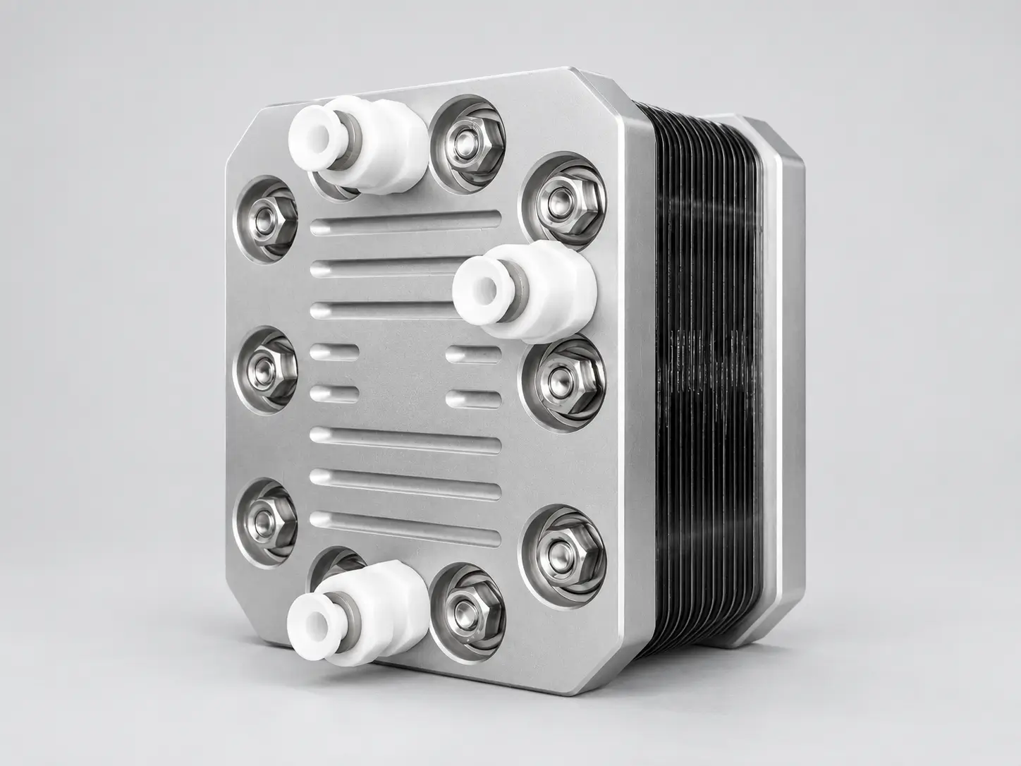
05 · Stack family
Reference Stack Hydrogen Output
1200–2000 mL/min H₂
Intermediate compact option controlled by duty profile, active area, cell count, current and voltage, water and heat removal.
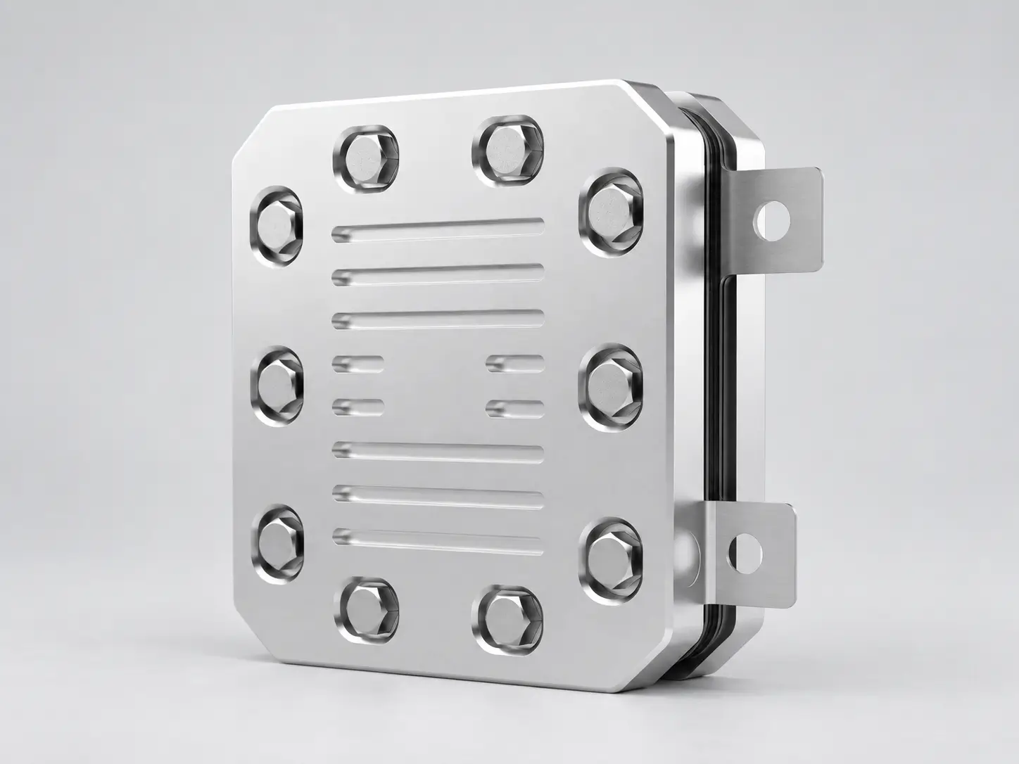
06 · Stack family
Reference Stack Hydrogen Output
600–1000 mL/min H₂
Standardized-envelope direction whose interfaces, performance, sealing and tests are frozen in the approved drawing and protocol.
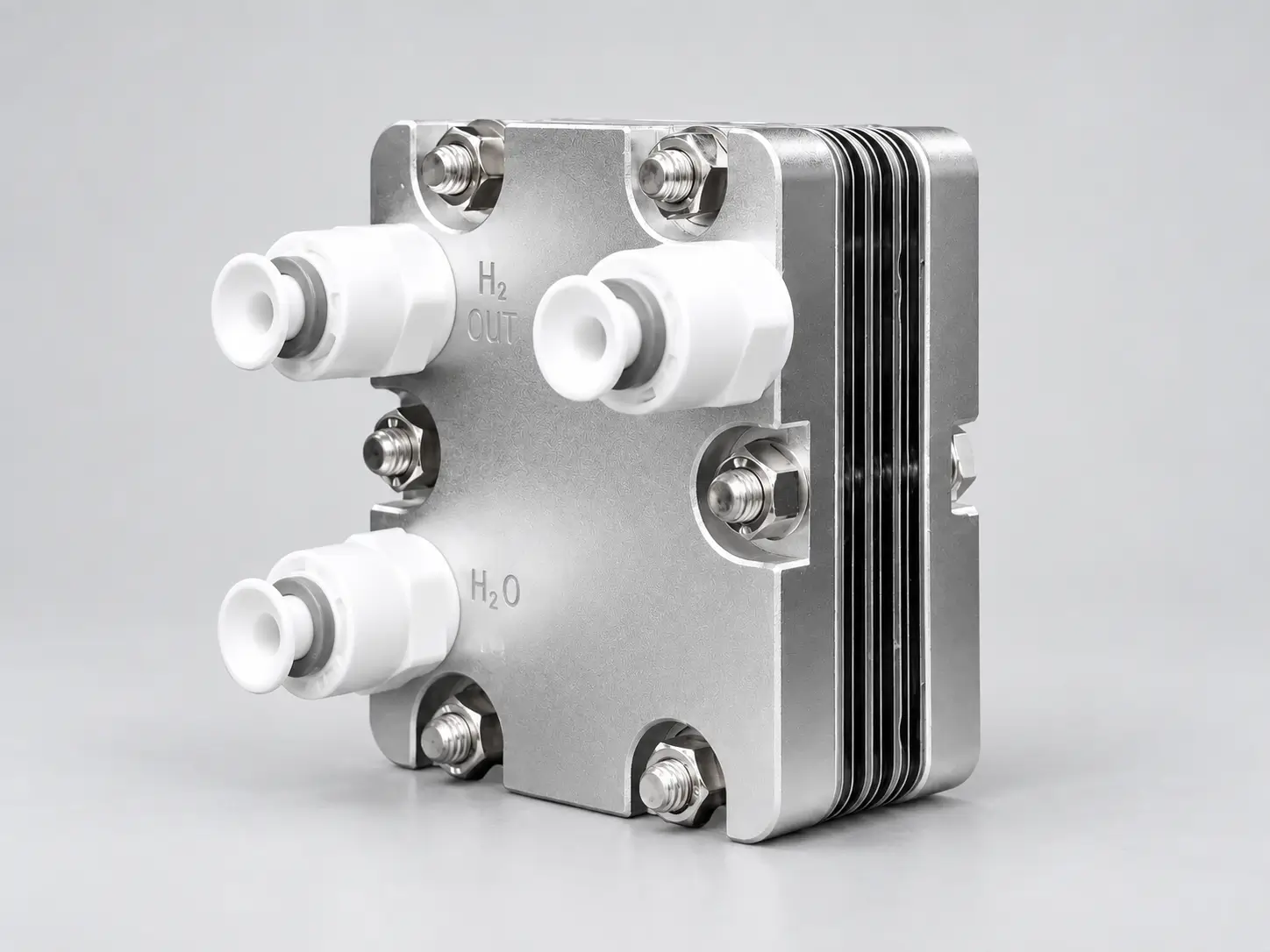
07 · Stack family
Reference Stack Hydrogen Output
300–450 mL/min H₂
Lower-output development or distributed-use direction with project-specific gas, pressure, water and control boundaries.

08 · Stack family
Reference Stack Hydrogen Output
40–200 mL/min H₂
Small research and OEM direction requiring a defined electrical point, gas measurement, safety, test protocol and scale-up boundary.
Performance boundary: Published output values are selection references for the stated stack family. Contractual output must identify the gas reference conditions, DC operating point, water quality, temperature, hydrogen and oxygen pressure, differential pressure, conditioning and stabilization procedure, measurement method and acceptance duration. A bare-stack output value does not define the hydrogen delivered by the complete electrolyzer system.
Unit note: Compact-stack values remain in the originally published mL/min units. They are not converted to Nm³/h without an agreed normal-condition basis.
Build a single matching table across hydrogen duty, electrical window, active area/cell count, pressure, water/thermal conditions, mechanical envelope and OEM interfaces.
| Decision group | Define before design freeze | Typical evidence |
|---|---|---|
| Hydrogen / electrical | Output, reference conditions, current/voltage/power, density denominator, duty and degradation basis | Polarization/performance data under stated conditions |
| Cell architecture | Active area, cell count, MEA/PTL/bipolar-interface specification and stack revision | Drawing, BOM/specification and traceability as ordered |
| Pressure / fluids | H₂/O₂ pressure, differential, water flow/quality, temperature, manifolds and purge/drain | Pressure/leak and flow-interface evidence |
| Mechanical | Compression, tie rods, end plates, seals, envelope, supports, ports and service access | Approved GA/interface drawing and inspection |
| OEM interface | Terminals, sensors, insulation, cooling, control/protection, transport and installation | ICD, inspection/test plan and release documents |
HELE can review an OEM stack requirement and define an order-specific build, interface and qualification scope. The approved drawing, test protocol and responsibility matrix control what is manufactured, verified and documented for the ordered stack.
01 · OEM Review
Review hydrogen duty, electrical window, water, temperature, pressure, differential pressure, operating profile, envelope and annual volume.
Typical output: stack design basis and open-interface list.
02 · Stack Configuration
Align active area, cell count, target current and voltage, stack envelope and operating point with the approved OEM requirement.
Typical output: proposed configuration and controlled performance basis.
03 · Interface Customization
Define manifolds, ports, electrical terminals, sensors, supports, end plates, tie rods, purge, drain, relief and service access.
Typical output: approved stack and interface drawing.
04 · Assembly Control
Control the agreed assembly sequence, component identity, alignment, compression, sealing, insulation, fasteners and in-process records.
Typical output: order-specific build and inspection records.
05 · Qualification Testing
Complete the specified leak, pressure, insulation, electrical or electrochemical checks under stated conditioning and test conditions.
Typical output: test data and release evidence defined by the protocol.
06 · Prototype to Series
Align prototype, qualification batch, approved revision, change control, traceability, packing and repeat-order documentation.
Typical output: agreed document register and production-release basis.
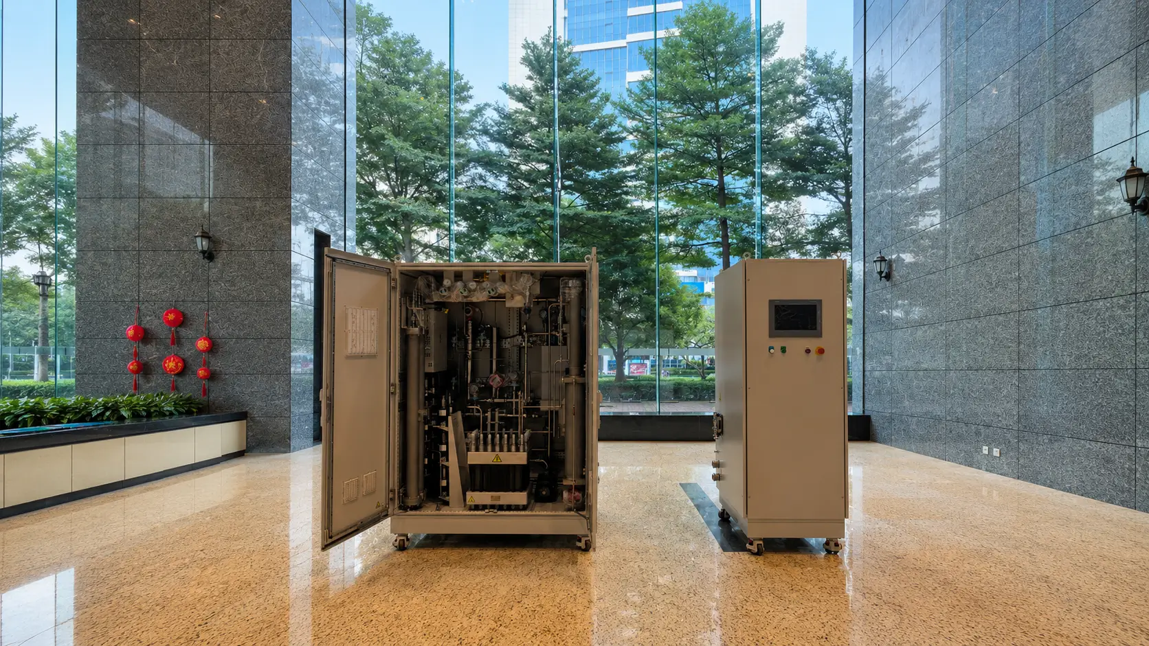
Unless specifically included and tested, the stack quotation does not by itself establish the performance or compliance of the surrounding system.
Order rule: define the stack test boundary separately from the balance-of-plant and delivered-gas boundary.
The public process is an overview. Actual component sources, manufacturing ownership, clean handling, build controls, compression/sealing route and test records are confirmed for the ordered stack.
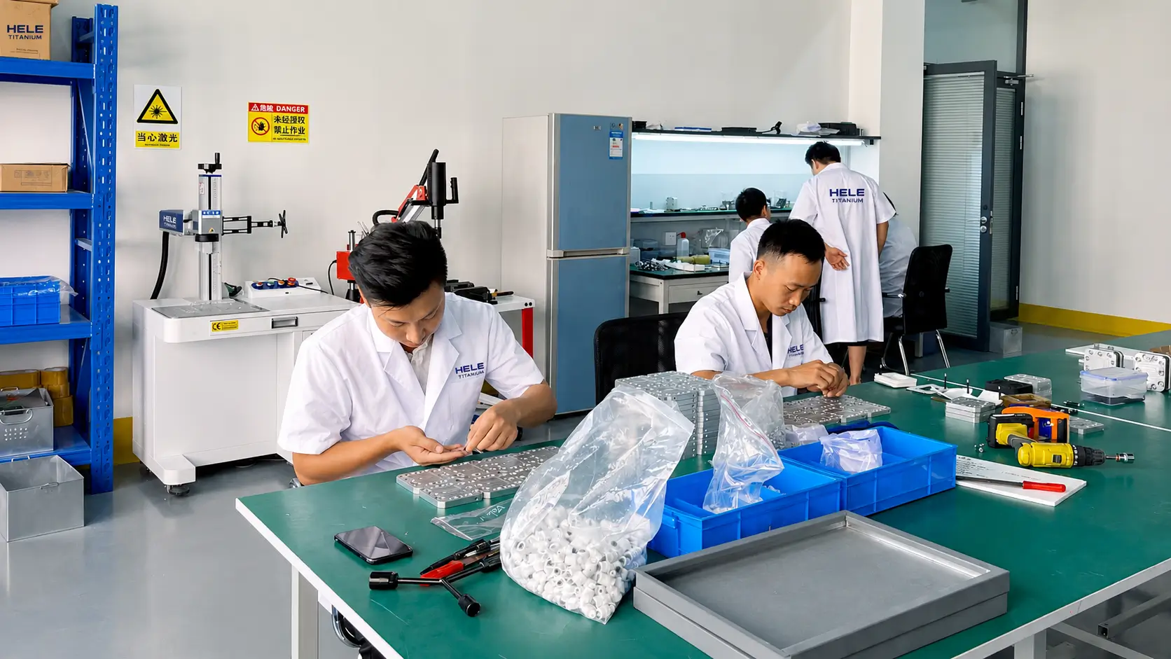
Confirm approved cell components, lot identity, cleanliness, handling and build revision.
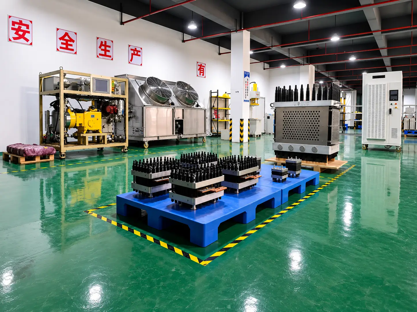
Control sequence, alignment, compression, seals, manifolds, fasteners and in-process records.
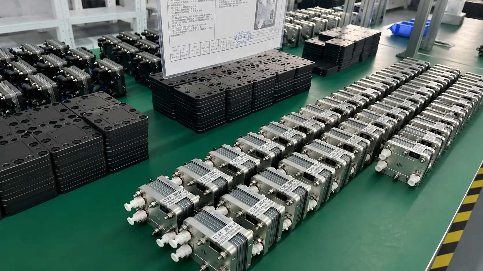
Verify ports, electrical contacts, insulation, tie rods, end plates and pressure/leak-test boundary.
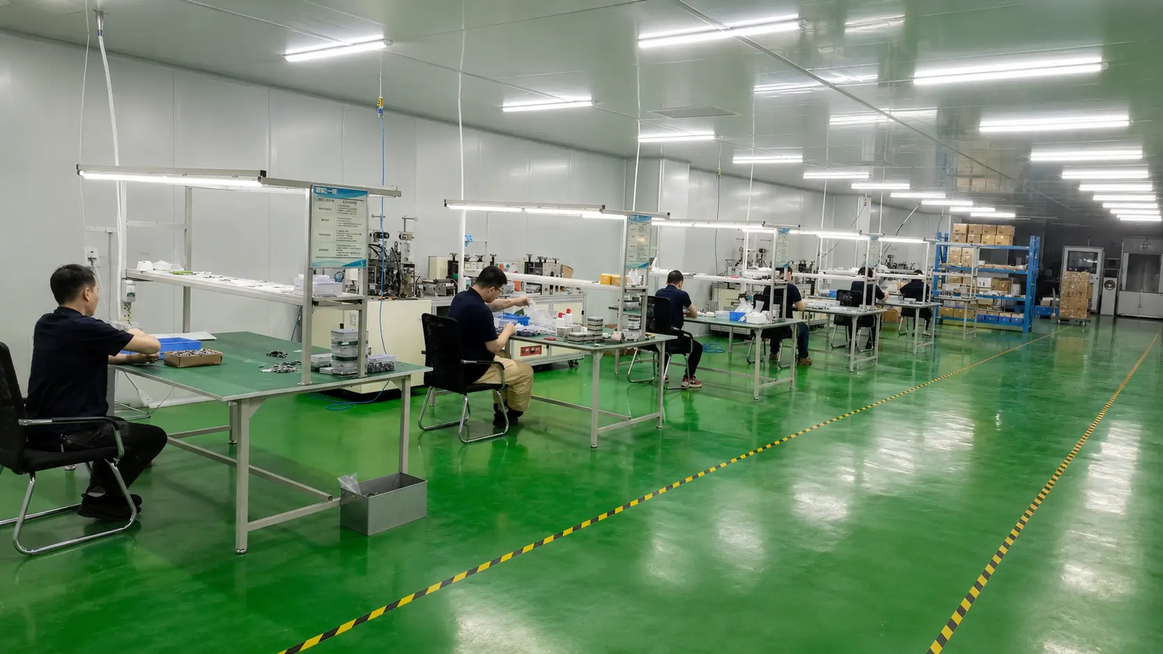
Complete agreed leak/pressure, electrical/electrochemical, inspection, documentation and packing release.
Five original application directions are retained. System-level results still depend on rectifier, water/gas loops, thermal management, controls and downstream equipment.

Define variable DC duty, cycling, ramp, start/stop, thermal response, BoP control and degradation measurement.
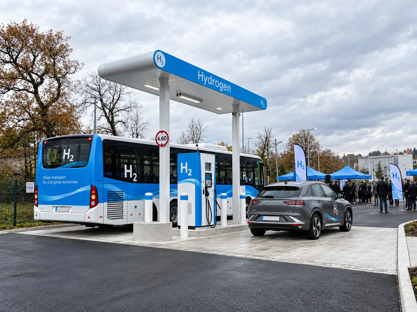
Separate stack pressure/output from drying, compression, storage, precooling and dispensing system scope.
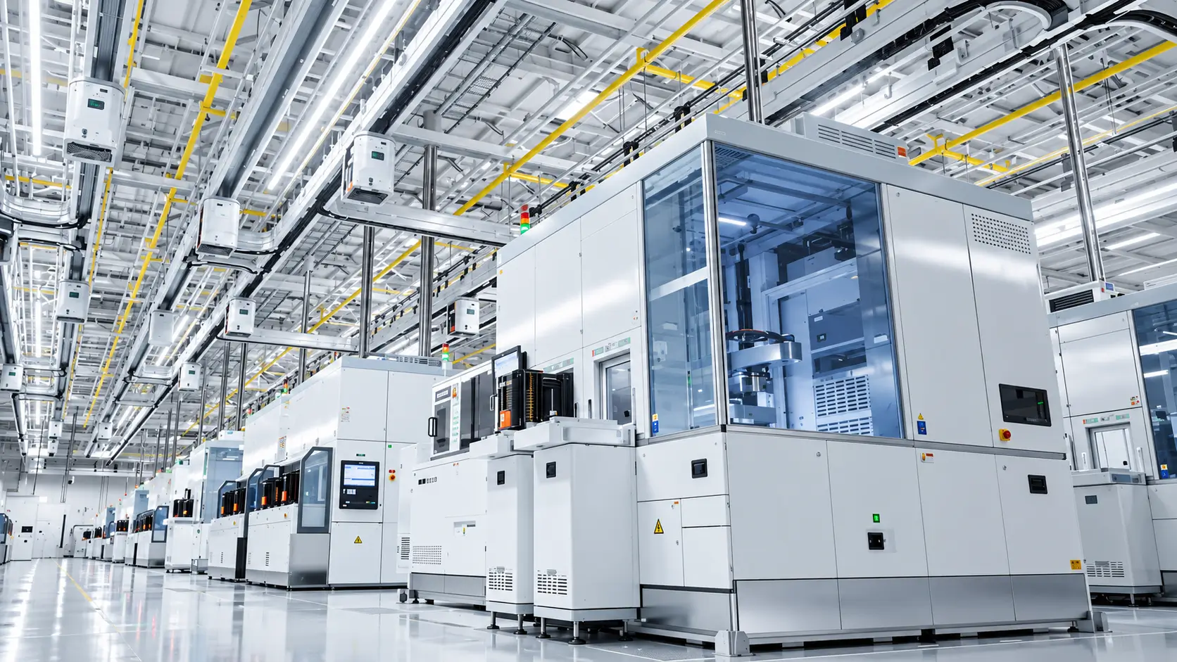
Specify gas-quality point, contaminants, pressure, redundancy, controls, monitoring and customer qualification.
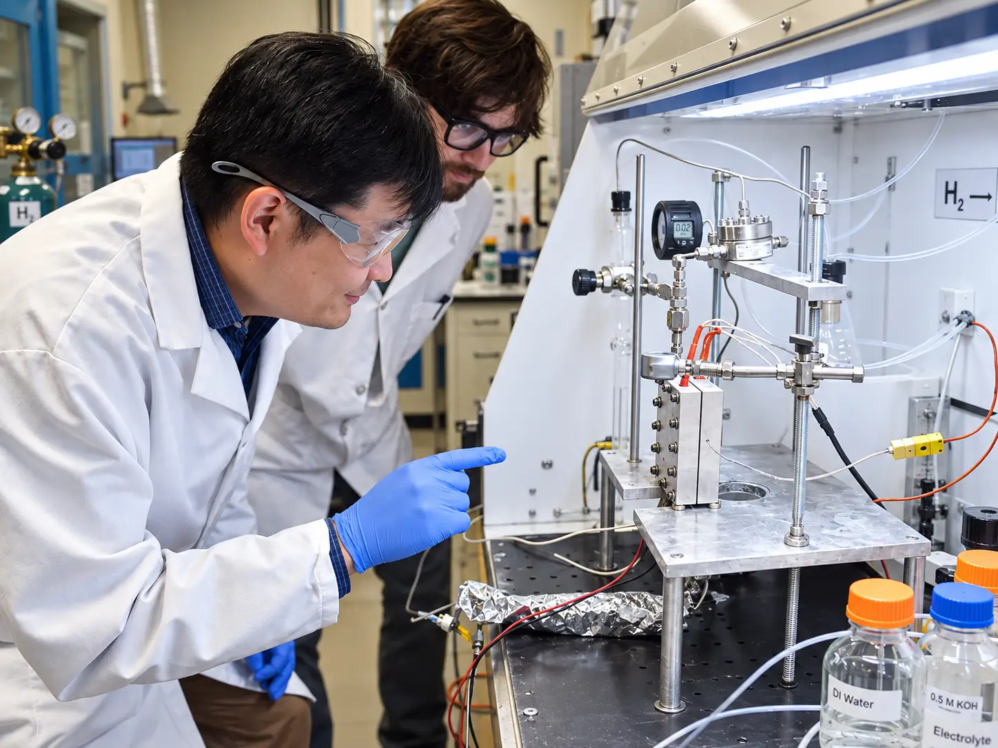
Control active area/cell count, instrumentation, pressure, safety, test matrix, data and scale-up boundary.
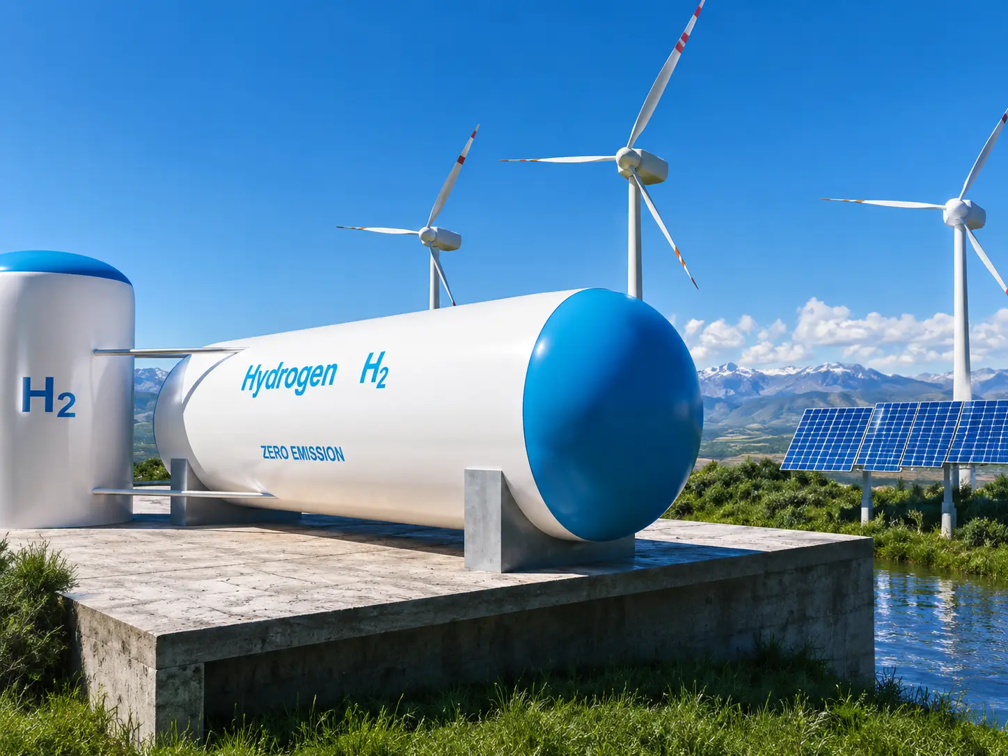
Define production profile, renewable/grid interface, storage/use, availability, dynamic operation and system boundary.
Specify conditioning, water, temperature, pressures, current/voltage steps, stabilization, hydrogen measurement, gas analysis, leak/crossover method, test duration and end point. Data from different setups are not automatically comparable.
Medium, separate/common boundary, test pressure, differential, duration and acceptance.
Current-density denominator, cell/stack voltage, temperature, pressure, flow and stabilization.
Sampling point, purge/conditioning, method, calibration, pressure and operating point.
Duty profile, cycles, duration, degradation calculation, end point, interruptions and exclusions.
DOE target boundary: DOE stack/system targets are development guideposts and state that performance, durability and cost targets must be met simultaneously on the same relevant stack or system. They must not be copied into an HELE datasheet as guaranteed product values.
A stack is an integration component, not a complete electrolyzer. Compare suppliers using the same cell architecture, operating envelope, performance conditions, mechanical interfaces, test plan and balance-of-plant assumptions.
No. A water-electrolysis stack consumes electricity and water to produce hydrogen and oxygen. A fuel-cell stack consumes hydrogen and oxidant to produce electricity, heat and water. Their reactions, flow fields, interfaces, materials, controls and performance metrics differ.
Provide required hydrogen output, current/voltage or power window, pressure and differential pressure, water quality and flow, temperature, duty profile, cell count or envelope constraints, manifolds, electrical interfaces, cooling, test protocol and annual volume.
No. Crossover and stack operation matter, but separators, dryers, purification, sampling point, pressure, purge and balance-of-plant design also affect delivered-gas specification.
State DC measurement boundary, hydrogen mass/volume reference conditions, test duration, beginning/end state, temperature, pressure, water, current density and whether auxiliary loads are excluded.
Only the defined pressure boundary under the stated medium, pressure, duration, temperature and acceptance method. It does not by itself prove electrochemical performance, purity, durability or system compliance.
Define duty profile, operating point and cycling, water quality, temperature, pressure differential, start/stop, end-of-life criterion, degradation method, test duration and exclusions. Accelerated testing is not a direct lifetime guarantee.
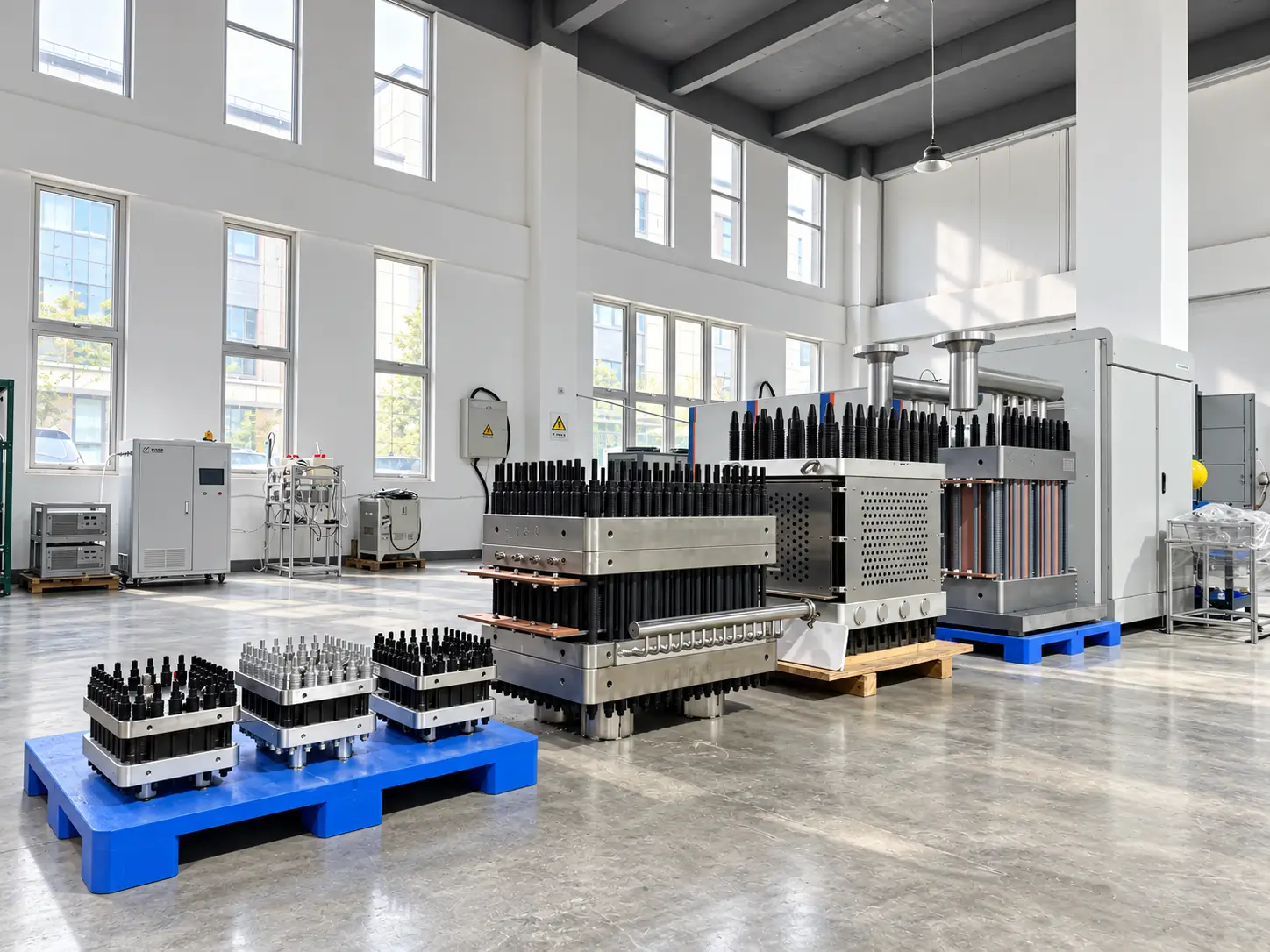
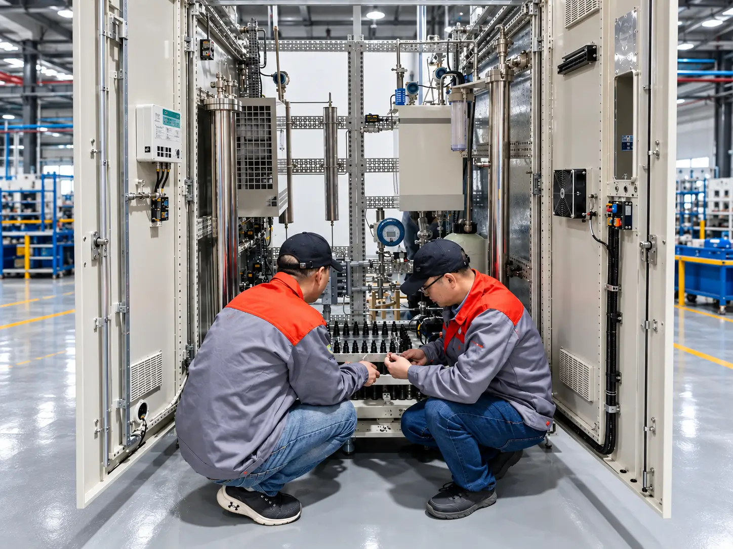
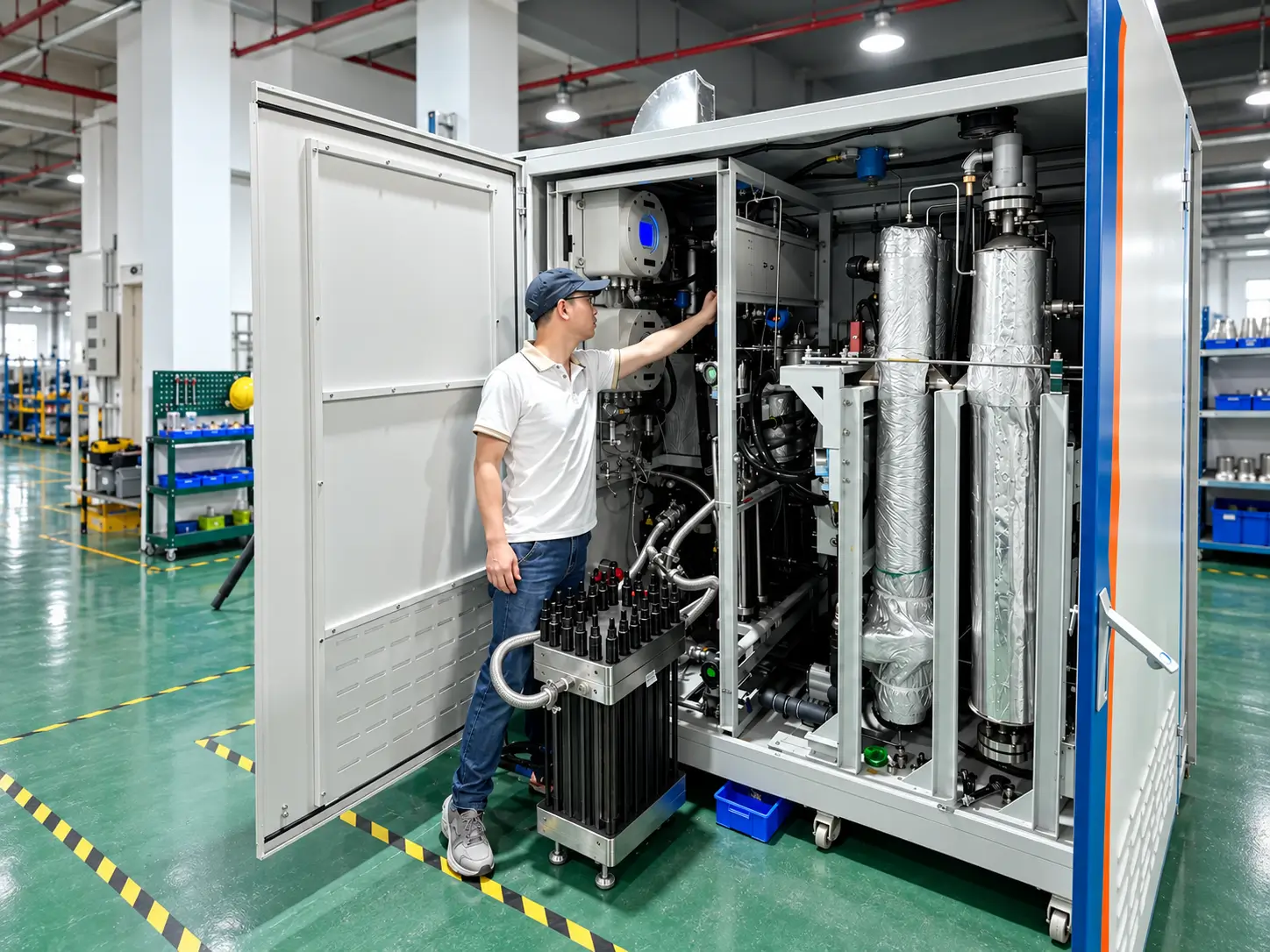
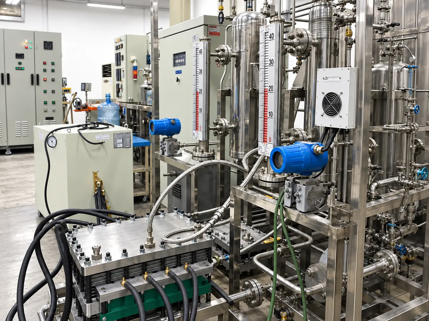
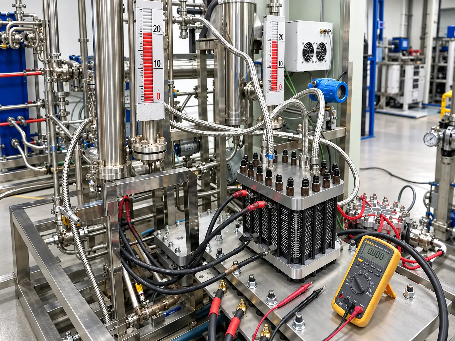
A visual overview of stack assembly, interface review, inspection, traceability and release activities. The exact component source, manufacturing ownership and evidence package are confirmed for each order.
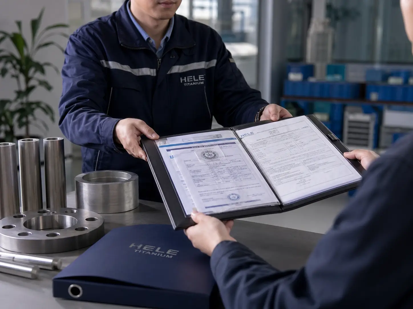
Send the interface drawing, electrical/fluid duty and test requirements currently available. Unknown items can remain open until the OEM design basis is aligned.