
MARINE SHAFT EARTHING · PROPELLER SHAFT PROTECTION
Shaft Earthing Devices for Marine Propulsion Systems
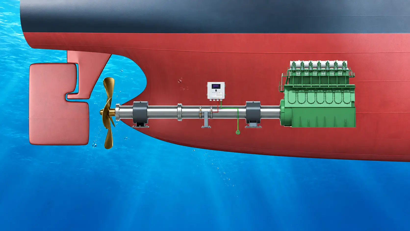
HELE supplies complete shaft earthing assemblies and replacement components for marine propulsion systems, including conductive slip rings, grounding brushes, brush holders, grounding cables and shaft-potential monitoring. Each configuration is reviewed against shaft diameter, RPM, available installation space, existing arrangement and monitoring requirements.
How the Shaft Earthing Assembly is Built
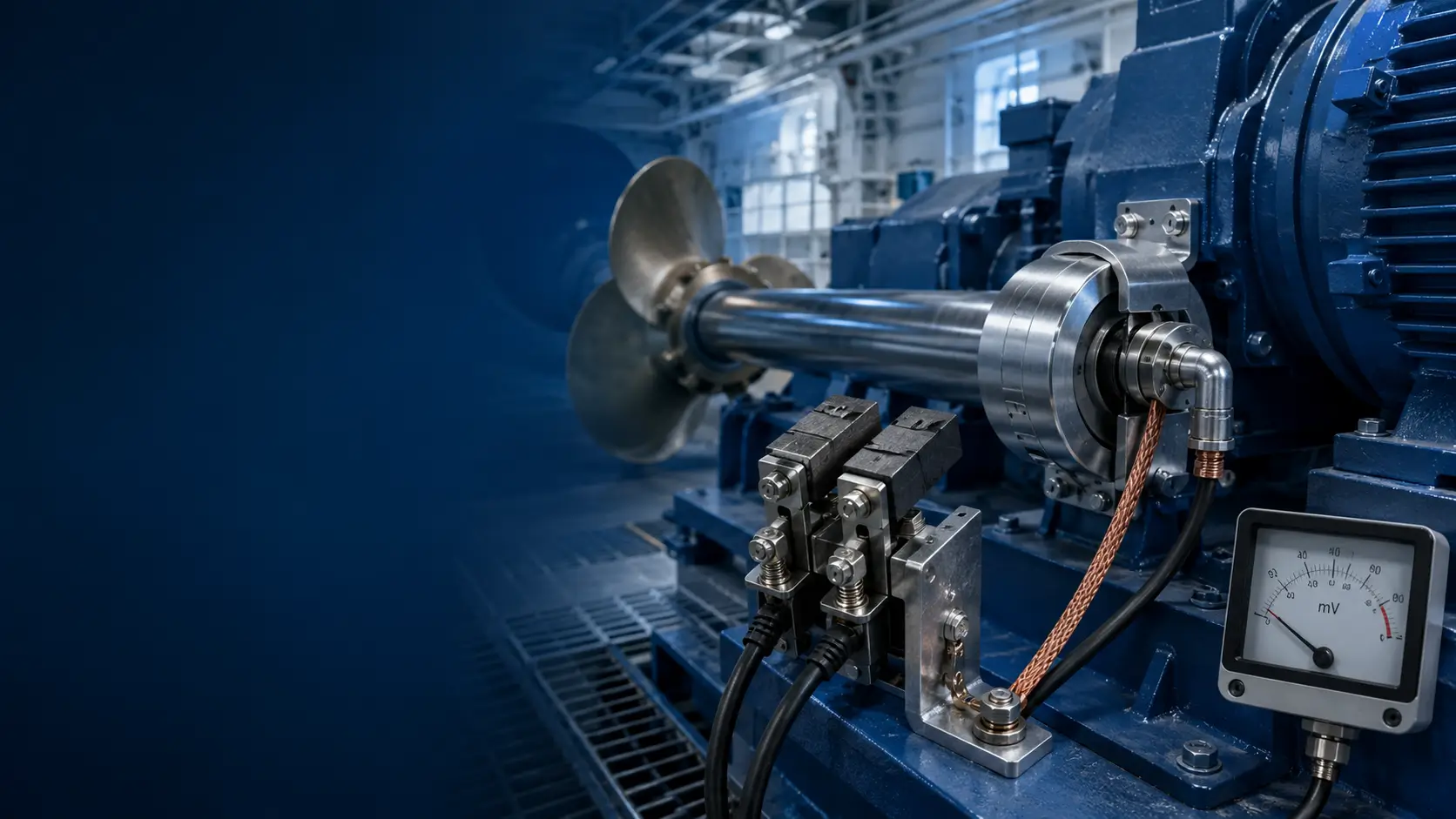
A marine shaft earthing device creates a low-resistance path to divert harmful shaft currents away from critical bearings. The system architecture relies on four core components working in synergy.
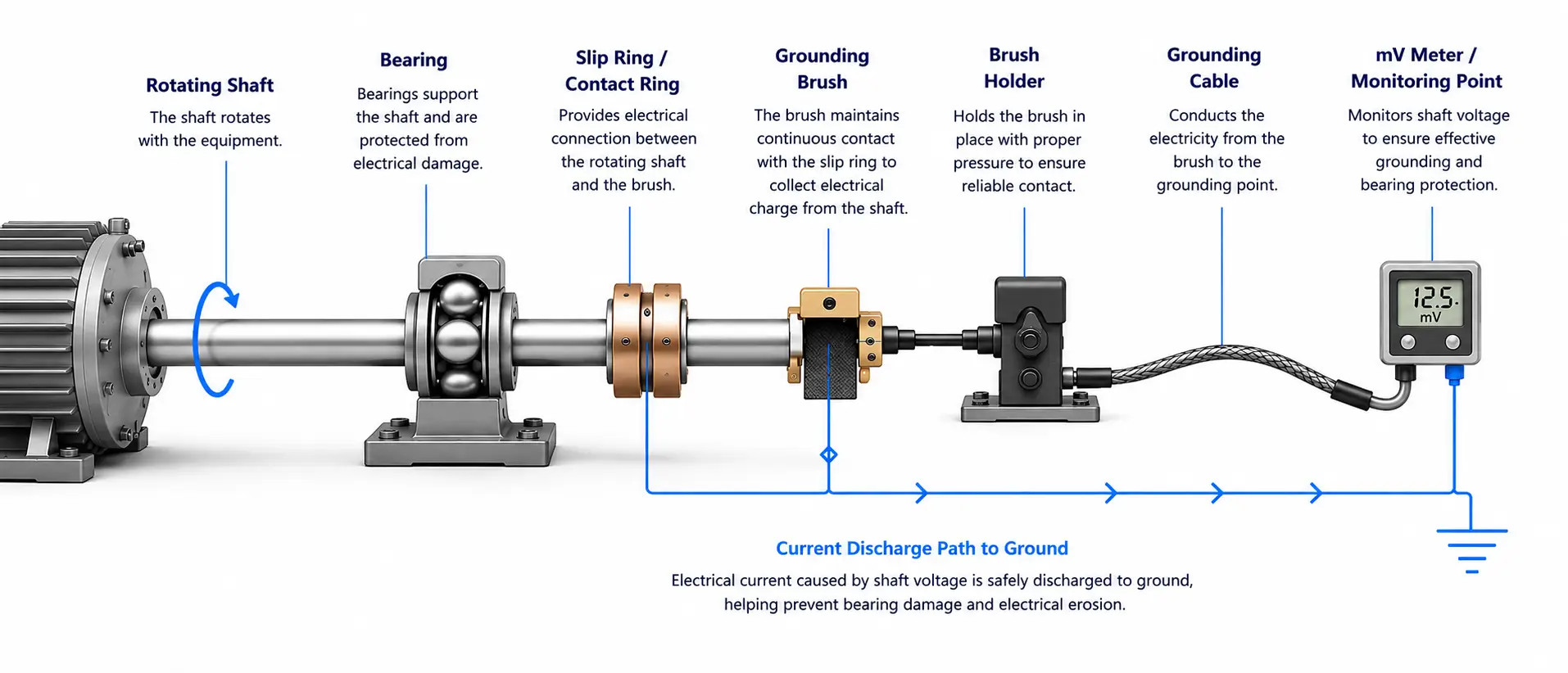
Conductive Slip-Ring Surface
Provides a stable, low-resistance contact track mounted on the rotating shaft to prevent mechanical wear and ensure high conductivity.
Earthing Brushes
Sacrificial conductive elements (e.g., silver-graphite) that maintain continuous sliding contact to transfer current safely to ground.
Brush Holder Assembly
Secures the brushes in position and applies consistent spring pressure to compensate for wear and vibration.
Shaft-Potential Monitoring
Measures the residual shaft-to-ground potential to verify the earthing path remains effective during operation.
Note: Acceptance criterion for shaft potential is to be confirmed against the approved project, class, owner or propulsion-system requirement.
Marine Shaft Earthing Systems & Components
Consolidated purchasing groups for newbuilds, retrofits, and routine maintenance of marine propulsion systems.
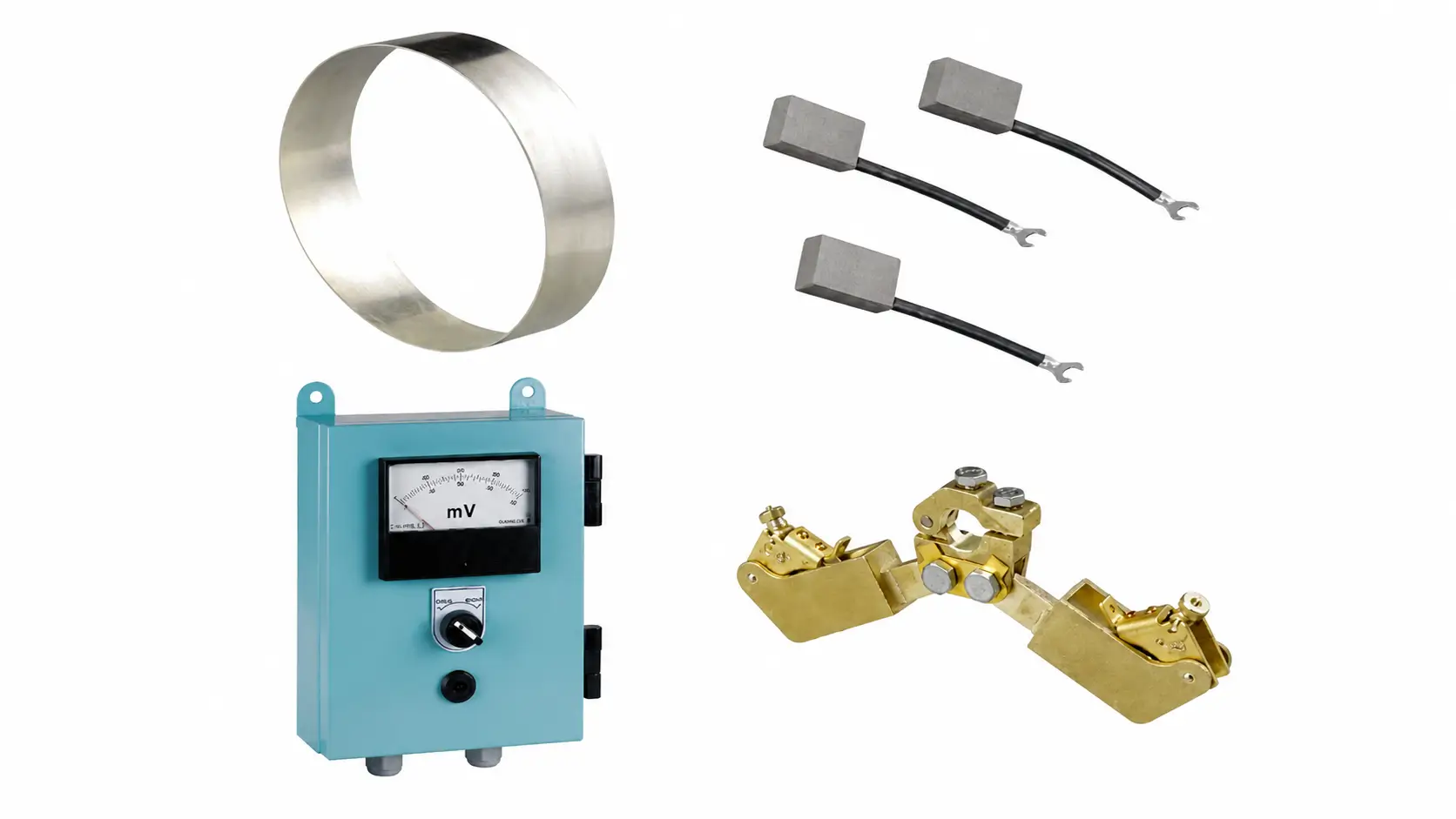
1. Complete Shaft Earthing System
Fully integrated marine packages including slip ring, brushes, holders, grounding cable, and monitoring meter. Sized to specific shaft requirements.
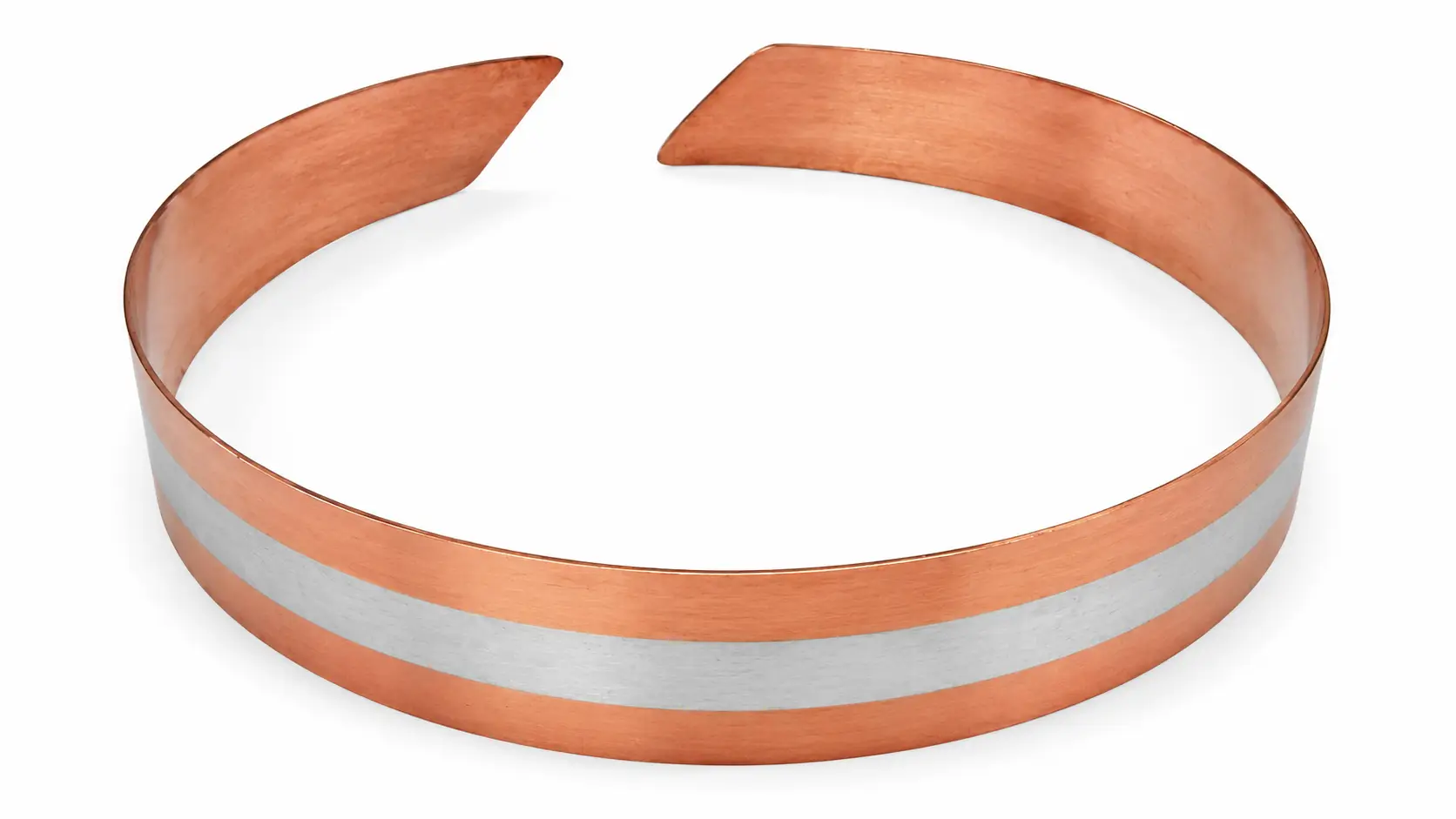
2. Silver Slip Ring / Grounding Ring
High-conductivity silver alloy slip rings and bands. Custom machined or supplied as split-bands based on exact shaft diameter to ensure a pristine contact track.
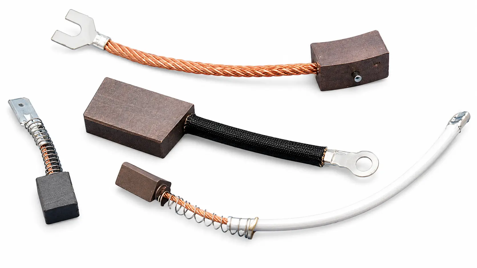
3. Grounding & Silver-Graphite Brushes
Sacrificial transfer mediums blending high conductivity with dry-lubrication properties. Available in standard and custom dimensions for replacement.
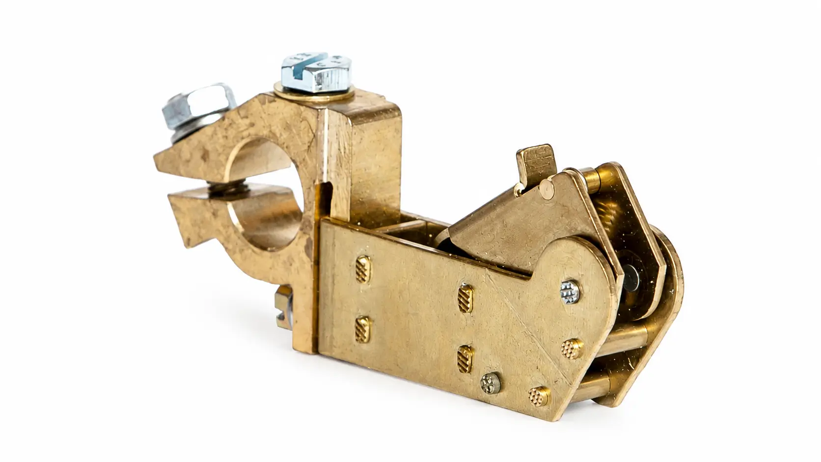
4. Brush Holder Assemblies
Single and double holder configurations with calibrated springs. Designed to maintain constant physical pressure against the slip ring despite vibration.
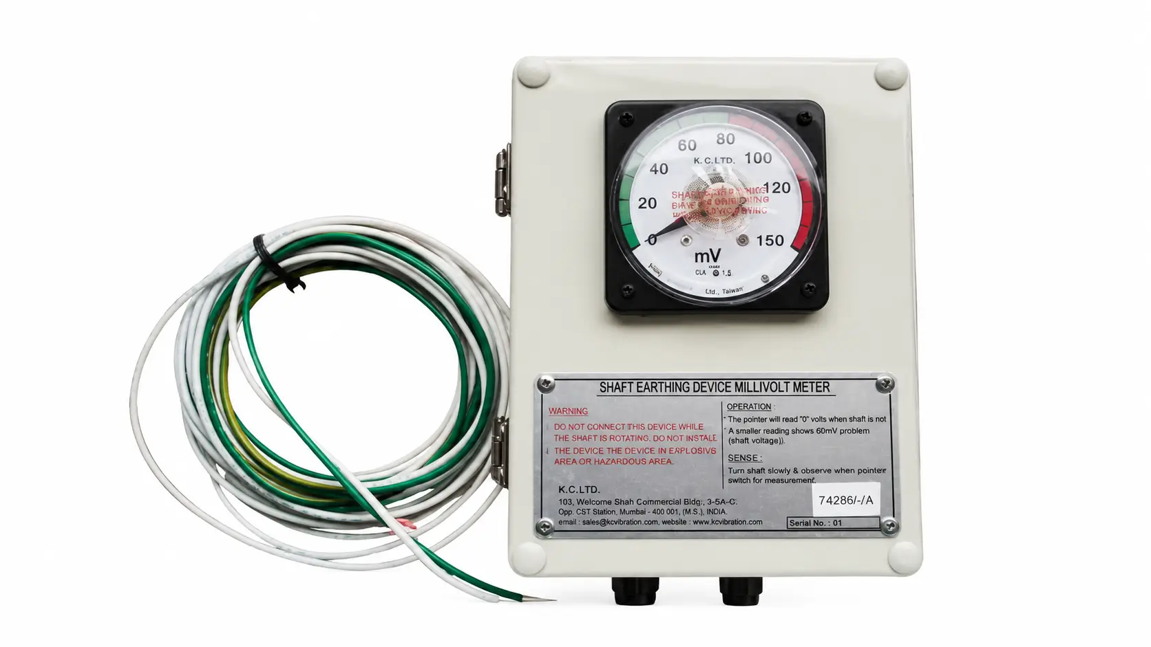
5. mV Monitoring & Alarm
Analog and digital meters to verify grounding integrity. Options available for control room alarm integration and remote signal output.
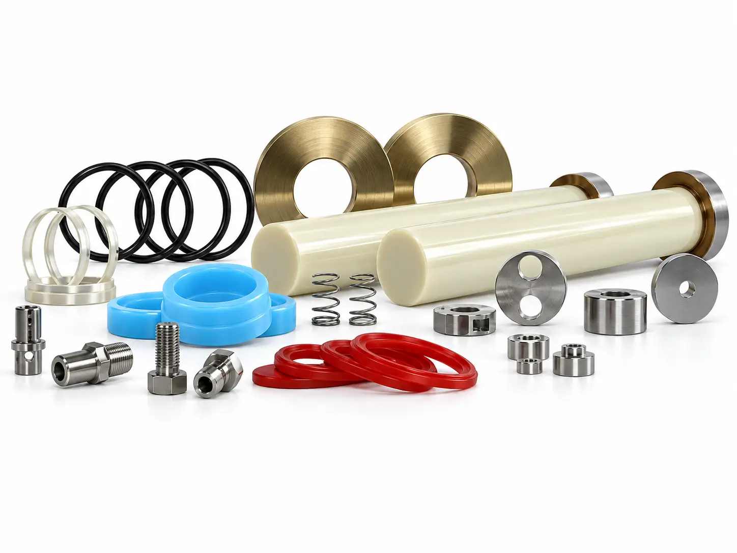
6. Replacement & Retrofit Kits
Custom retrofit packages designed to fit existing layout constraints during drydock maintenance or emergency repairs.
Technical Specification & Integration Inputs
Standard specification parameters required for accurate system design and manufacturing.
| Parameter | Specification / Input Required |
|---|---|
| Equipment Type | Marine Propeller Shaft (Primary) / Generator / VFD Motor |
| Shaft Diameter | To be confirmed by application review. |
| Shaft RPM | To be confirmed by application review. |
| Slip Ring Material / Width / Mounting | Silver alloy / Custom width / Split-band or solid ring |
| Brush Material | Silver-Graphite (Recommended for marine) / Silver / Carbon |
| Brush Quantity | Determined by current load and redundancy requirements. |
| Holder Arrangement / Contact Pressure | Single or double brush holders with calibrated springs. |
| Shaft / Hull Potential Acceptance | To be confirmed against approved project or class requirement. |
| Contact Resistance / Continuity | To be confirmed by application review. |
| mV Monitoring | Analog or Digital meter options available. |
| Alarm / Signal | Optional relay alarm or 4-20mA output for control room integration. |
| Available Axial / Radial Space | Requires dimensional layout or photos for retrofit fitment. |
| Environment | Marine engine room / Offshore / Industrial. |
| Mounting Drawing | Provided upon system specification approval. |
| Spare Parts | Replacement brushes and springs available upon request. |
Project & Retrofit Review Process
To ensure the shaft earthing device performs reliably and fits the physical constraints of the vessel, HELE conducts a structured technical review before manufacturing.
-
Equipment & Shaft Confirmation of shaft diameter, material, and operating RPM.
-
Existing Arrangement & Envelope Review of available axial and radial space, current mounting brackets, and layout photos.
-
Electrical & Monitoring Requirement Defining the current source, grounding path, and whether local analog or digital alarm monitoring is required.
-
Project Requirement Alignment with class approvals, shipyard schedules, or drydock timelines.
Applications & Product Boundary
Designed for heavy-duty rotating equipment across marine and industrial sectors.
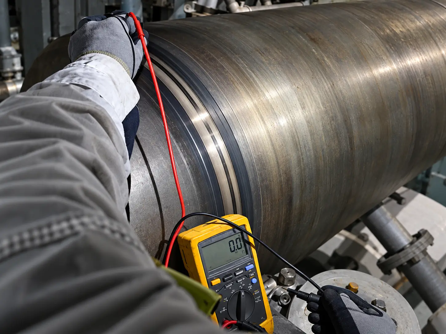
Important Note: Marine shaft earthing is the primary focus of this page. Industrial VFD shaft grounding is a related secondary application supported by our engineering team, but the core design parameters prioritize marine propulsion systems.
Marine Propeller Shafts PRIMARY
Protection against galvanic and static potentials to prevent main bearing and gearbox damage.
Ship Generators & Auxiliaries
Reliable grounding for critical onboard power generation equipment.
Offshore Rotating Equipment
Corrosion-resistant systems suitable for humid, salt-spray environments on platforms and FPSOs.
Industrial VFD Motors SECONDARY
Mitigation of high-frequency common-mode voltages induced by pulse-width modulation.
Generators & Turbines
Heavy-duty grounding solutions for large-scale power generation and rotating mass.
Retrofit Projects
Custom bracket and holder designs to replace obsolete or failing earthing devices in existing spaces.
Installation & Maintenance
Proper installation and routine inspection are critical to maintaining a low-resistance path. A compromised system forces current back through the bearings.
Installation Focus
- Ensure the Contact Surface (slip ring) is securely mounted and clean.
- Verify Brush Alignment is perfectly perpendicular to the contact track.
- Confirm correct Contact Pressure via the holder springs.
- Establish a short, heavy-duty Grounding Path directly to the hull or frame.
Maintenance Focus
- Conduct routine Wear Inspection of sacrificial brushes.
- Check Monitoring meters for abnormal mV spikes indicating poor contact.
- Clean carbon/graphite dust accumulation from the holder assembly.
Note: Replacement intervals depend on RPM, environment, and current load. Fixed intervals must be established based on operating evidence.
Inspection, Testing & Documentation
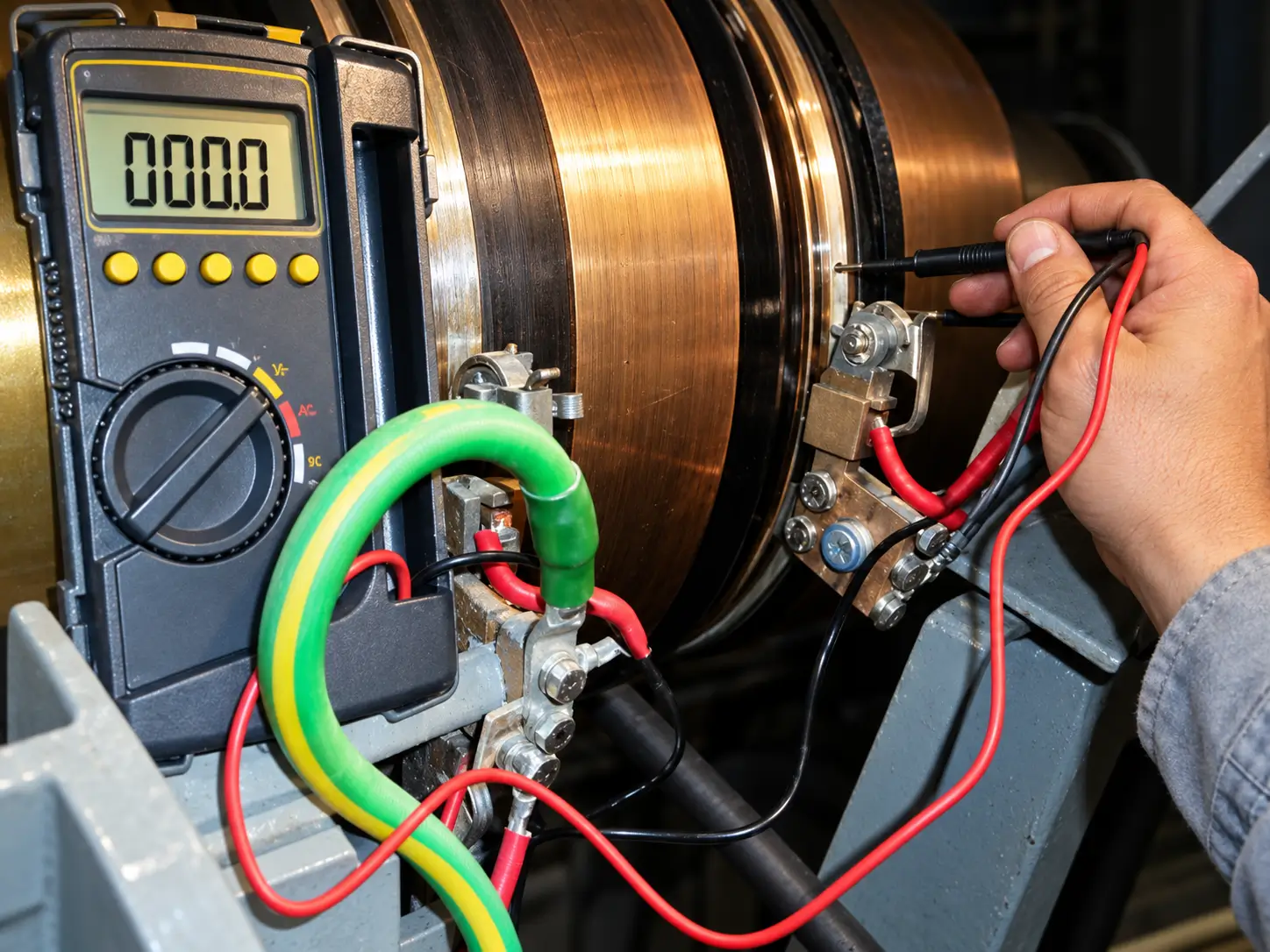
Quality control records and project documentation provided to support shipyard, class, and owner requirements.
Quality Control & Testing
- • Slip-Ring Dimensions & Surface verification
- • Brush Material / Dimensions check
- • Holder Alignment & Assembly inspection
- • Electrical Continuity testing
- • Contact Resistance under agreed conditions
- • mV Meter / Monitoring Function check
- • Alarm / Signal Check where specified
- • Identification & Packing verification
Project Documentation
- • Approved Drawing
- • Component Specification
- • Inspection Record
- • Electrical Test Record
- • Monitoring Information
- • Installation / Operation Instructions
- • Spare-Part List
Frequently Asked Questions
1. What is the function of a shaft earthing device?
2. What components are included in a complete system?
3. What engineering inputs are required for selection?
4. Can the system be retrofitted to existing vessels?
5. How does the monitoring and alarm function work?
6. What inspection and testing is performed before delivery?
TECHNICAL RFQ
Request Shaft Earthing Review & Quotation
Submit your equipment type, shaft diameter, RPM, axial/radial space, existing slip ring details, monitoring requirements, and class requirements. Our engineering team will review the parameters to recommend the appropriate shaft grounding configuration.
Direct Email: sales@heletitanium.com
Phone: 86-13857402537