Jetty and pier piles
Review distributed mounting around piles, pile groups, tidal exposure, coating interfaces and inspection access.

Fixed Marine ICCP · MMO Anode Assemblies
Fixed marine structures require anode assemblies that meet both electrical duty and exposed mounting conditions. HELE can configure MMO tubular, disc, rod or custom assemblies for piers, jetties, offshore frames, seawalls and seawater intakes.
The mounting and protection design for a fixed structure should be reviewed separately from a vessel hull ICCP arrangement.
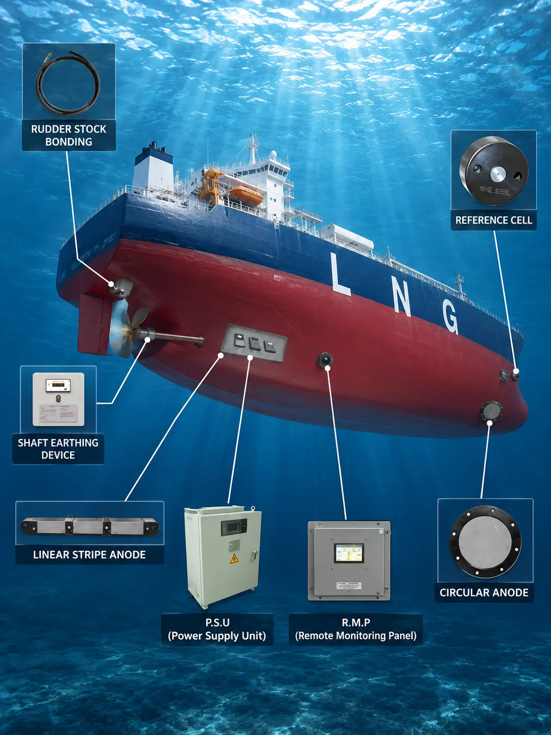
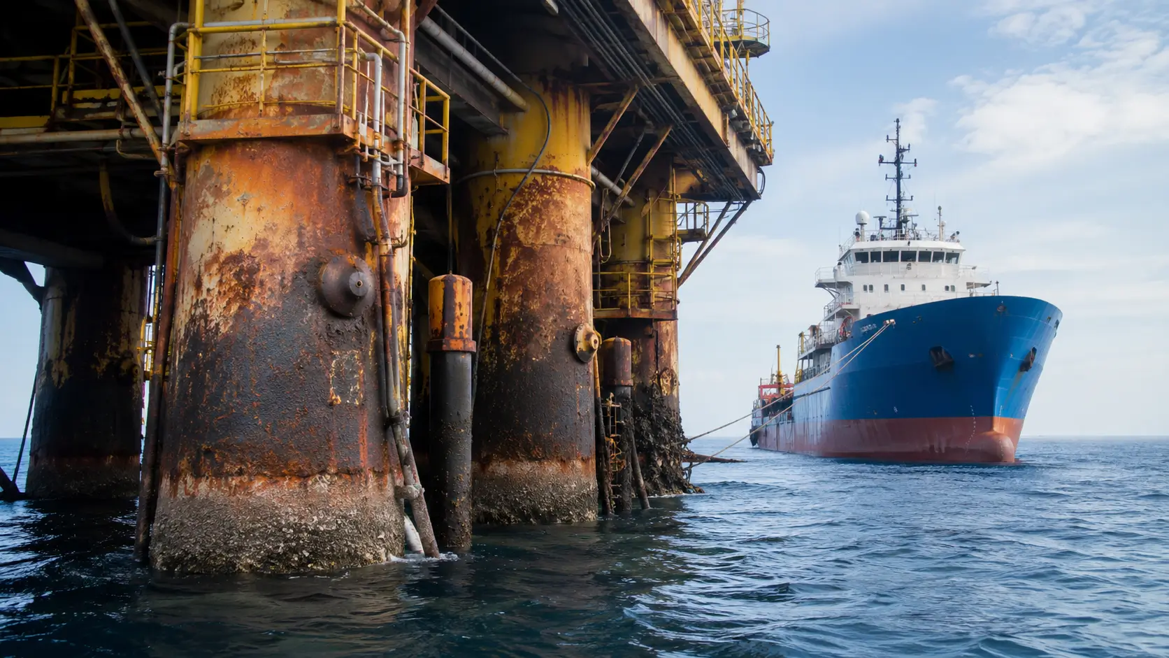
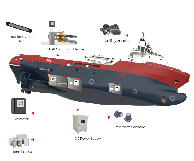
Fixed marine ICCP systems can protect jetties, piers, offshore jackets, seawalls, intake structures, sheet piling and other immersed steel. The anodes discharge current into seawater while a controlled power source, reference electrodes and monitoring arrangement maintain the project-defined protection criteria.
This page addresses fixed structures rather than automatically treating ship-hull systems as equivalent. Mounting loads, wave and current exposure, burial or shielding, cable routes, diver access, coatings and local current distribution must be reviewed for each asset.
Choose the anode form together with its mounting, dielectric shielding, cable protection and inspection strategy.
Review distributed mounting around piles, pile groups, tidal exposure, coating interfaces and inspection access.
Coordinate anode assemblies with jackets, risers, subsea frames, installation loads and remote monitoring.
Evaluate local current distribution, coating condition, cable routing and anode protection from impact.
Account for flow, screens, debris, nearby materials, access and interaction with anti-fouling systems.
The selected assembly should combine electrochemical duty with a mechanically credible mounting and cable-sealing design.
Best considered when: a robust tubular element is mounted on a stand-off, sled, frame or project-specific support.
Confirm: tube geometry, coating/loading, support, dielectric shield, cable exit and handling loads.
Best considered when: a compact low-profile assembly suits localized or distributed mounting on a designed support.
Confirm: disc size, mounting stud/flange, shield, cable seal, recess and inspection access.
Best considered when: a slender element suits frames, intakes or localized marine mounting under a defined duty.
Confirm: rod dimensions, holder, insulation, cable connection, support and flow exposure.
Best considered when: the project requires a sled, frame, guard or integrated mounting that standard forms do not provide.
Confirm: loads, materials, isolation, fabrication drawing, lifting, cable armor and inspection method.
High local current density near an anode can affect coating and distribution. The marine CP design may use dielectric shields, stand-off distance, zoning and controlled anode placement to manage this interface. Reference-electrode locations and control philosophy should represent the protected zones rather than simply being placed near the anode.
Design control: Do not publish or reuse a generic seawater current density, output or shield size. Final values depend on structure geometry, coating condition, water properties and CP design.
Use these inputs to define the quotation and the approved anode supply schedule. The CP designer confirms the final design values.
| Decision | Why it matters | Evidence to provide |
|---|---|---|
| Structure and zones | Defines current distribution and mounting locations. | General arrangement, immersed area, zones and coating condition. |
| Water environment | Conductivity, temperature and flow affect operation. | Salinity/conductivity, temperature, depth, tidal range, velocity and fouling. |
| Electrical duty | Controls anode size, loading, cable and zones. | Design current, duty per anode, design life and control philosophy. |
| Mechanical mounting | Must withstand installation and service loads. | Mounting drawing, loads, support materials, isolation and guards. |
| Cable route | Submerged connections are critical reliability interfaces. | Cable type/length, armor, seals, penetrations and mechanical protection. |
| Inspection access | Influences replaceability and lifecycle plan. | Diver/ROV access, retrieval method, test plan and maintenance strategy. |
Project review
The active element alone does not define a marine installation. The support, dielectric interface, cable path and inspection access can control durability and current distribution.
Map immersed steel area, tidal and splash zones, coating condition, flow, fouling and possible burial or shielding.
Confirm current by protection zone, operating voltage, active area, coating basis and the planned reference-electrode positions.
Provide support, guard, stand-off, isolation, lifting and installation-load requirements in the approved drawing.
Define insulation, armor where required, route, termination, sealing and access for inspection or replacement.
Define responsibilities in the purchase specification. HELE can configure and manufacture agreed anode components or assemblies; complete system engineering is not automatically included.
Inside HELE
HELE can align MMO dimensions, active area, agreed support or shield features, factory cable and seal, identification and packing to the approved marine drawing. Electrical and seal tests require project-specific methods and acceptance values.
Confirm the supplied titanium form, dimensions, active zone and order identification.
Control the specified coating basis, connection, cable, seal, backfill or mounting features included in the order.
Record continuity, connection or insulation results when the inspection plan defines method and acceptance limits.
Match drawings, inspection records, labels and packing documentation to the approved supply schedule.
Field installation, CP calculations, commissioning and performance acceptance follow the agreed project responsibility matrix.
Inquiry
Send the structure layout, immersed zones and mounting drawing. HELE can review the anode, support and cable scope against the required electrical duty.
Prefer email?
sales@heletitanium.comFactory & Engineering Center
Titanium Valley, Baoji City, Shaanxi Province, China