
At first, buying a replacement MGPS anode can look straightforward. You have the old part, a material name and a few dimensions. It may seem that the supplier only needs to copy what is already there.
But a replacement has to do more than fit. It must perform the same job, work with the controller and connect correctly to the existing seawater system.
What this guide covers: consumable copper, aluminum and ferrous anodes used in controlled-current MGPS or ICAF systems. Electrochlorination MGPS, ICCP and galvanic sacrificial cathodic protection use different equipment and design rules. They are outside the scope of this guide.
1. First, identify the system and the anode’s job
The name MGPS tells you the goal: limit marine growth. It does not tell you how a particular system achieves it. Some systems use controlled-current anodes. Others generate an oxidant from seawater. ICCP and ordinary sacrificial anodes serve a different purpose.
Before you measure the old part, identify the type of system and the job of the component. This prevents three different items—an anti-fouling anode, a corrosion-conditioning anode and a cathodic-protection component—from being treated as interchangeable.
| System or component | Primary purpose | Power and control | What to verify before purchase |
|---|---|---|---|
| Anode-based MGPS / ICAF | Reduce biological settlement in seawater intakes and downstream equipment; some systems also include a corrosion-conditioning anode. | Controlled low-voltage direct current from a dedicated controller or transformer-rectifier. | Anode role, material, controller channel, design current, flow path, mounting, insulation and cable. |
| Electrochlorination MGPS | Generate an oxidant from seawater and inject it into the water circuit. | Electrolyzer, power supply, dosing and control equipment. | Cell technology, process capacity, dosing basis, water chemistry and system-specific spares. This guide does not cover cell selection. |
| ICCP | Provide controlled cathodic protection to immersed metal structures. | Impressed current with reference electrodes and dedicated control logic. | Protection design, electrode type, reference electrodes, structure and controller compatibility. |
| Sacrificial cathodic protection | Protect metal through galvanic action. | No external controller. | Alloy, structure potential, exposed area, design life and attachment method. |
Start with the records you can actually find
- Vessel or facility name, project number and seawater circuit.
- System maker, model, controller nameplate and channel identification.
- Original anode drawing, part number and revision, if available.
- Installation point: sea chest, strainer, filter, intake line or other approved location.
- Reason for replacement: planned renewal, abnormal consumption, damage, leakage, low output or unavailable legacy part.
A part number is a useful starting point, not a complete specification. Use it to trace the original item, then check it against the drawing, controller data and the actual installation.
2. Match the anode material to the job it has to do
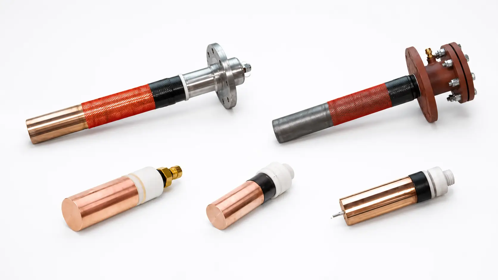
Copper, aluminum and ferrous anodes are not three versions of the same consumable. They can do different jobs. In a common anode-based system, copper provides the anti-fouling action. A second anode may support corrosion conditioning in compatible pipework.
That does not mean the second material can be chosen from a catalogue. Its role and material must match the approved system design and the metal used in the seawater circuit. The current relationship between the anodes must match as well.
| Anode | Typical system role | Buyer checks | Common error |
|---|---|---|---|
| Copper | Anti-fouling ion source for the treated seawater stream. | Approved material specification, active mass and geometry, required current, installation point and expected flow distribution. | Assuming more current always improves protection. Output must remain within the approved operating basis. |
| Aluminum | Corrosion-conditioning role in systems designed for compatible ferrous pipework. | Pipework material, original system arrangement, alloy specification, controller channel and required current relationship. | Replacing a ferrous anode with aluminum without an engineering review. |
| Ferrous / iron | Corrosion-conditioning role in systems designed for compatible copper-nickel pipework. | Pipe alloy, original design intent, material specification, controller settings and evidence of compatibility. | Ordering “iron” as a generic commodity without defining composition and system duty. |
Use the table to ask the right questions. Do not use it to choose a material on its own. If the proposed material differs from the installed arrangement, record the change and ask the responsible engineer to review it before releasing the purchase order.
3. Follow the seawater through the system
The anode works at one point in the system, but the treatment has to travel with the seawater. So ask a simple question: where does the water go after it passes the anode?
A nominal pipe diameter cannot answer that question. You also need the flow path, pump operation, salinity and temperature range, downstream equipment and any bypasses or separate sea chests.
| Input | Why it changes the decision | Useful evidence |
|---|---|---|
| Seawater route and equipment sequence | Shows which strainers, coolers, pumps or box coolers are expected to receive treated water. | P&ID, seawater schematic, marked-up general arrangement or photographs. |
| Maximum and normal flow | Supports the system output and distribution review. | Pump curve, design flow sheet, commissioning record or measured operating data. |
| Salinity and temperature range | Influences conductivity, electrochemical behavior and the operating envelope. | Design basis, trading route, site water analysis or seasonal records. |
| Pipework and equipment metallurgy | Determines whether the proposed corrosion-conditioning anode follows the existing design intent. | Line list, material specification, drawings or verified field identification. |
| Operating hours and target service period | Connects current demand with the required consumable mass and spare strategy. | Voyage profile, maintenance plan, dry-dock interval and controller-hour records. |
| Fouling and maintenance history | Helps distinguish a sizing problem from blocked flow, incorrect settings or uneven distribution. | Inspection photographs, cleaning records, current logs and failure reports. |
A new anode cannot correct every problem in the seawater circuit. Fouling may continue if water bypasses the anode, a pump runs only occasionally or treatment stops for long periods. That can happen even when the replacement itself is correct. Inspection and mechanical cleaning still belong in the maintenance plan.
4. What should you take from the controller?
The controller is one of the most useful sources of information in a replacement review. It can show how the installed circuit has been operating—but only if you read the right values.
Start with the channel count, normal current and voltage, alarm history and operating mode. Then record polarity, terminal arrangement and any current limit used in service. The controller, cable and anode form one circuit, so review them together.
Three current values that are not the same
- Controller capacity is the maximum the power unit can supply under its rated conditions.
- Design current is the target assigned to the anode or circuit in the approved system design.
- Operating current is what the installed system actually delivers. Read it together with voltage, alarms and service conditions.
The controller’s maximum rating is not the current assigned to one anode. A low operating current does not automatically mean that the anode is too small, either. The controller, cable, terminal, insulation, seawater conductivity, anode condition and local flow can all change the reading.
Ask how the proposed service life was calculated. The calculation should state the assumed output, operating hours, material utilization or minimum remaining allowance, material basis and environmental limits. Without these assumptions, a service-life figure is only an estimate. It is not a guaranteed replacement date.
5. Will the replacement fit the existing installation?
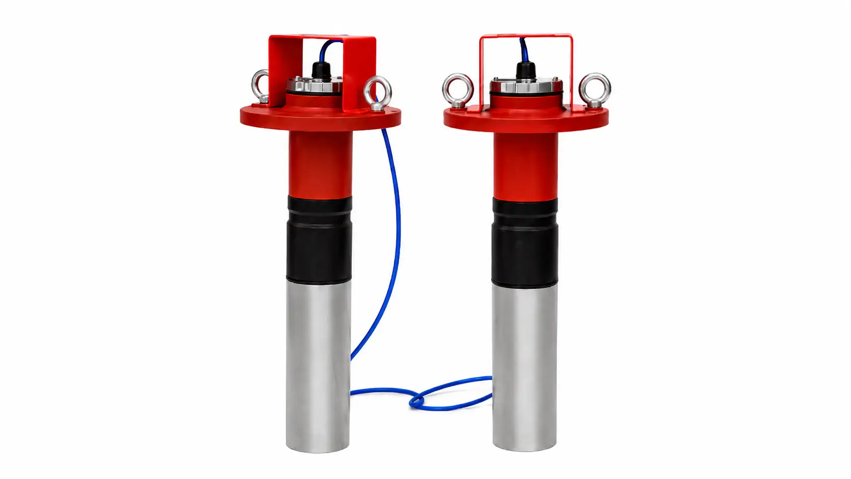
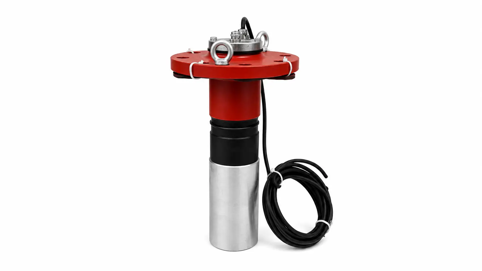
A replacement may fit inside the available space and still be impossible to install correctly. The flange may be different. The seal may not suit the pressure boundary. The cable may be too short, or the insulation arrangement may not match the original design.
Start by fixing the vessel-side interfaces on an approved drawing. Other manufacturing details may vary only where that drawing allows them to vary.
| Interface | Record on the RFQ or drawing | Acceptance question |
|---|---|---|
| Consumable body | Material specification, active length and diameter, overall length, net consumable mass and any taper or profile. | Will the exposed geometry and material match the approved electrical duty? |
| Mounting | Flange standard and drilling, thread, stud, sleeve, housing, orientation and available removal clearance. | Can the item be installed without modifying the vessel-side interface? |
| Insulation | Insulating sleeve, bush, washer, coating or other separation required by the original design. | Can electrical isolation be verified before and after installation? |
| Pressure boundary | Seal type, gasket, gland, cofferdam or double-gland arrangement, design pressure and any test requirement. | Who is responsible for the pressure-containing parts and leak test? |
| Cable and termination | Cable type, conductor size, length, insulation, gland, lug or connector, polarity identification and bend constraints. | Will the supplied termination reach and connect to the correct controller channel? |
Do not copy a pressure-boundary detail from another vessel. Use the controlled drawing for this installation. Check its pressure class, sealing arrangement, test scope and approval requirements before accepting a flange, gland or cofferdam design.
6. Prove equivalence on one controlled drawing
If the original part is obsolete or unavailable, a catalogue photograph is not enough. Compare the old and proposed items on one controlled drawing. Show what is the same, what performs the same function and what has changed.
A visible difference is not automatically a problem. But someone must review it, and the approval route must be clear. The comparison below keeps these decisions from getting lost in emails or general supplier notes.
| Comparison line | Existing item | Proposed item | Required disposition |
|---|---|---|---|
| Function and system location | Record original duty and channel. | State the proposed duty and channel. | Must remain consistent with the approved system architecture. |
| Material | Specification, grade or verified composition. | Proposed specification and certificate basis. | Approve any difference before manufacture. |
| Active geometry and mass | Drawing values or measured condition. | Drawing values and tolerances. | Review against the current and service-life basis. |
| Mounting and seals | Flange, thread, sleeve, gland and gasket. | Matching interface with proposed seal scope. | No site modification unless separately approved. |
| Cable and termination | Length, conductor, gland and terminal. | Proposed cable assembly. | Confirm electrical capacity, reach and connection. |
| Inspection and documents | Original or owner-required records. | Supplier document list and inspection plan. | Resolve missing evidence before order release. |
Sometimes the worn anode on board is the only reference available. Measure it, but remember that it no longer shows the original condition. Its active length, mass and seal may have changed in service. Mark every value as measured, calculated or assumed. This shows the reviewer where judgment is still needed.
7. Agree the evidence before manufacture
“Full inspection” sounds reassuring, but it does not tell the supplier what to inspect or what records to provide. Name each required record and the purchasing risk it is meant to control.
Each record answers a different question. A material record confirms composition and traceability. A dimensional report checks the consumable body and installation interfaces. A pressure or leak test is relevant only when the supplied parts form part of the pressure boundary.
| Evidence | Purpose | Define before order |
|---|---|---|
| Approved drawing and revision | Controls dimensions, interfaces, cable and marking. | Approval route, language, review time and change control. |
| Material certificate or analysis | Links the supplied anode to the ordered material basis. | Certificate type, tested elements, heat or batch traceability. |
| Dimensional and mass report | Verifies the consumable body and installation interfaces. | Critical dimensions, tolerances, net mass and measuring stage. |
| Electrical checks | Confirms continuity through the conductor and isolation where required. | Test points, acceptance values and report format. |
| Pressure or leak test | Supports acceptance when supplied parts form part of the pressure boundary. | Test scope, pressure, duration, medium, witness and exclusions. |
| Photographs and marking | Connects the finished item, terminal and packaging to the order. | Required views, nameplate data, serial or batch number. |
| Packing and preservation record | Protects long or insulated assemblies during storage and transport. | Support points, moisture protection, lifting limits and storage period. |
Who provides what?
- The owner or operator provides the installed-system information and accepts changes.
- The system designer or responsible engineer controls the design basis and operating settings.
- The anode supplier manufactures and inspects the item within the agreed supply scope.
- The yard or installer controls vessel-side preparation, installation and pressure integrity outside the supplier’s scope.
- The commissioning party records settings and baseline performance.
The contract may allocate these tasks differently. What matters is that the split is written down before the order is released.
Be specific about approval. Does the project require class, flag, owner or regulatory review? Which documents need approval or witnessing? Must the supplier provide an approved component, supporting records or both? The phrase “marine certified” does not answer these questions.
8. Build a baseline during commissioning
Commissioning creates the reference point for future maintenance. At a minimum, record the installed anode, controller channel, settings, initial readings and seawater operating condition.
Without that record, a later inspection may show that performance changed, but not when the change began or what else changed at the same time.
- Before installation: verify drawing revision, marking, material record, cable length, seal kit, insulation components and transit condition.
- During installation: follow the approved isolation and vessel-safety procedure; confirm orientation, sealing surfaces, electrical isolation, cable routing and terminal polarity.
- Before energizing: complete required continuity, insulation and leak checks and record the responsible person.
- At commissioning: record channel, setpoint, actual current and voltage, alarm state, seawater condition and relevant pump or flow status.
- During service: trend current and voltage, controller hours, alarms, visible consumption, fouling observations and maintenance events.
Look at the trend, not just one reading. A stable current can still hide poor treatment distribution downstream. A changed reading may come from seawater conductivity or the operating state rather than a defective anode. Electrical data is easier to understand when you compare it with flow and inspection records.
9. If performance changed, diagnose before reordering
Premature consumption, low output and continued fouling are symptoms. They do not identify the cause. If you simply reorder the same geometry, the same problem may return.
Use the table as a starting point for the investigation, together with the vessel’s electrical-isolation, confined-space and pressure-system procedures.
| Observed condition | Check first | Evidence to retain |
|---|---|---|
| Low or no current | Controller alarm and settings, correct channel, cable continuity, terminals, insulation, anode condition and seawater conductivity. | Controller readings, alarm log, electrical test results and photographs. |
| Rapid or uneven consumption | Actual current against design basis, operating hours, local flow, exposed geometry, material and electrical connection. | Remaining dimensions or mass, current history, flow status and material traceability. |
| Fouling continues downstream | Water path, pump operation, bypasses, treatment interruption, anode location, current trend and maintenance condition of strainers and coolers. | System schematic, inspection locations, fouling photographs and operating timeline. |
| Leakage or moisture at the cable entry | Seal and gland condition, installation torque or procedure, pressure boundary and cable damage. | Leak location, seal parts, installation record and test result. Isolate under the approved procedure before intervention. |
| Corrosion concern after a material change | Pipework metallurgy, original corrosion-conditioning arrangement, controller settings and approved deviation. | Material records, before-and-after inspection, water data and engineering approval. |
Keep the readings, photographs and inspection notes with the replacement record. They help the supplier and responsible engineer distinguish an anode issue from a controller, cable, flow or installation problem.
10. Are the quotations really comparable?
Two quotations can show the same anode description and still cover very different scopes. One may include the cable, gland, seals, inspection reports and export packing. Another may quote only the consumable body.
Compare each offer against the same scope sheet before you compare the total price. Otherwise, the lowest unit price may simply be the least complete offer.
- Same anode material specification, active geometry, mass and design duty.
- Same flange, thread, sleeve, insulation, seal and cable assembly.
- Same drawing-approval cycle and included revisions.
- Same inspection, certificate, test-report and witness requirements.
- Same packing, delivery term, lead-time basis and spare quantities.
- Every deviation listed in a separate schedule rather than hidden in general notes.
Before you release the order
Check the system duty, material and current basis first. Then confirm the mechanical and cable interfaces, required documents and responsibility for installation and approval. If an item is still open, record it as a hold point with an owner and due date. Do not let it disappear into the general purchase order notes.
11. What should you send with the RFQ?
You do not need a perfect document package before asking for a review. Send the original drawing if you have it. If you do not, use clear photographs and a marked measurement sheet. The important part is to show which values are confirmed and which are still uncertain.
System and service
- Vessel, facility or project
- System maker and model
- Controller nameplate and channel
- Installation location and seawater circuit
- Flow, salinity and temperature range
- Pipework and equipment materials
Anode and commercial scope
- Material and intended duty
- Drawing, part number and dimensions
- Operating current and service history
- Mounting, seal, cable and termination
- Quantity, spares and delivery date
- Inspection, documents and approvals
If the anode failed or was consumed earlier than expected, include the operating history, remaining dimensions or mass, controller records and photographs. These records help the reviewer investigate the cause instead of simply copying the previous geometry.
Common purchasing questions
Questions buyers often ask
Are MGPS anodes the same as sacrificial anodes?
No. The anodes in this guide work as part of a controlled direct-current anti-fouling system. Ordinary sacrificial anodes provide galvanic cathodic protection without a controller. Confirm which system is installed before you specify the replacement.
What does a copper anode do in an anode-based MGPS or ICAF system?
In a typical anode-based system, the copper anode provides the anti-fouling function. Controlled current releases copper ions into the seawater stream, where they help limit biological settlement downstream. The required output still depends on the approved system design and operating conditions.
Can aluminum and ferrous anodes be substituted for each other?
No—not from the material name alone. Their corrosion-conditioning role depends on the pipework material, original system design and controller arrangement. Review the approved drawing and material basis before considering a substitution.
Can an MGPS replacement anode be ordered from diameter and length only?
Usually not. Diameter and length tell you part of the mechanical story, but not the active mass, electrical duty, insulation, seal, cable termination or seawater conditions. Those details can change whether the replacement fits and works as intended.
How should the replacement interval be estimated?
Start with the measured condition of the remaining anode, then review operating current, service hours, consumption history, seawater conditions and the approved replacement threshold. Calendar age by itself is not a reliable basis.
What should be included in an MGPS anode RFQ?
Send what you have: the vessel or asset, system maker and model, anode role and material, drawing or measured dimensions, controller data, installation location, pipework material, cable and mounting details, quantity, document requirements and delivery date. Mark anything that still needs confirmation.