

“Titanium diaphragm” is not one standardized product. A tweeter dome, pressure-sensor membrane, diaphragm-seal element and industrial flexible component may share a material family while having different geometry, loads, interfaces, tests and approval authorities.
1. Define the Diaphragm's Actual Role
State whether the purchase is for an audio dome, speaker or compression-driver component, a sensor membrane, a pressure diaphragm, a diaphragm-seal element or another drawing-based industrial part. Identify whether the supplier delivers only the formed titanium component or also trimming, holes/tabs, joining, coating, cleaning, subassembly or functional testing.
| Component role | Primary purchase inputs | Typical validation boundary |
|---|---|---|
| Audio diaphragm component | Profile, thickness, edge, surround/interface, tooling, sample and surface | Component geometry plus OEM assembly/acoustic testing |
| Sensor membrane | Active diameter, support, displacement, pressure, temperature, media and interface | Component inspection plus calibrated sensor validation |
| Pressure or seal diaphragm | Differential pressure, direction, overpressure/vacuum, cycles, media, joint and leak boundary | Applicable code/customer plan plus assembly proof/burst/leak/cycle testing |
| Drawing-based industrial part | Function, load case, material, geometry, interface and inspection | Order-specific component and system qualification |
2. Freeze Product-Definition Authority
List the drawing, 3D model, section/profile data, approved physical sample, specification and purchase-order revision. State which source controls each characteristic and how conflicts are resolved.
- If a sample is authoritative, define the master sample ID, storage, allowed handling and measurement plan.
- If a drawing controls, define datums, section locations, units, tolerances and notes.
- If a model controls, state the file/revision and how profile, thickness, edge and surface requirements are represented.
- Do not accept “same as sample” when critical characteristics have no measurable acceptance rule.
3. Record the Service and Load Case
Diaphragm behavior depends on the complete load history, boundary conditions and assembly. Define normal and exceptional conditions rather than one nominal value.
Frequency range, excursion, drive level, temperature, assembly preload, damping, voice-coil and adhesive/joint context.
Media, differential pressure and direction, static/dynamic profile, overpressure, vacuum, temperature, cycles and support.
Corrosion chemistry, humidity, contamination, cleaning, radiation or other exposure where applicable.
Permanent set, crack, leak, drift, resonance, distortion, interface damage or another defined limit.
4. Specify Grade, UNS, Material Standard and Condition
State the titanium Grade or alloy, UNS where required, material specification and revision, starting form, ordered condition and heat/lot traceability. Grade selection must reflect forming, fatigue/cycle duty, corrosion, joining, stiffness, strength and qualified system performance.
ASTM B265 covers titanium and titanium-alloy strip, sheet and plate within its scope. It can support starting-material control, but it does not define the formed diaphragm. ASTM F67 and ISO 5832-2 address unalloyed titanium material for surgical-implant manufacture within their scopes; neither converts a formed component into an approved medical device.
Do not write “Grade 1 for audio,” “Grade 2 for pressure” or “Grade 5 for extreme service” as universal rules. Confirm availability in the required thickness and condition, forming route, properties and application qualification.
5. Control Thickness Before and After Forming
Specify nominal thickness, tolerance, measurement method and locations. Define whether the criterion applies to incoming strip/sheet, the finished formed component or both. Forming can redistribute thickness, and flexible geometry may be distorted by inappropriate contact measurement.
- Define center, transition, corrugation, flange or other measurement zones.
- State permitted local thinning or thickness distribution where function requires it.
- Agree destructive or non-destructive verification and sampling.
- Separate certificate thickness from finished-component thickness evidence.
6. Define Diameter, Dome, Corrugation and Profile
Provide measurable geometry: overall and active diameter, dome height, section radii, cone angle, corrugation count, pitch, depth, root/tip radii, annulus, flange, tabs, holes, edge and interface features. Use datums and profile sections that can be repeated in production and inspection.
- Define free-state geometry and any inspection fixture or preload.
- State orientation and clocking of asymmetric tabs, holes or ribs.
- Specify profile tolerance and comparison method, not only a nominal CAD surface.
- For flexible parts, agree handling time and temperature before measurement if they affect results.
7. Specify Surface, Edge, Cleanliness and Appearance
State which surfaces are functional, cosmetic, joining or no-touch areas. Define scratches, dents, tool marks, waviness, discoloration, contamination and edge acceptance with measurable or controlled reference criteria.
- Define trim method, burr limit, edge break and crack-free requirement.
- State cleaning method, prohibited residues, handling and packaging cleanliness.
- For bonding or welding surfaces, define preparation and time-to-join controls where relevant.
- Use an approved visual standard or limit samples when appearance matters.
8. Control Tooling, Prototypes and Golden Samples
Tooling can be a major part of diaphragm repeatability and commercial scope. Define who owns the tool, what it includes, expected maintenance, storage, revision, replacement, transfer and end-of-life terms.
| Stage | Buyer and supplier should agree | Release gate |
|---|---|---|
| Feasibility | Material/thickness, geometry, forming limits, quantity, route and open risks | Quotation assumptions and exceptions |
| Prototype | Tool type, sample quantity, inspection plan and assembly test owner | Measured prototype plus required system results |
| Golden sample | Sample ID, limits, storage, handling, comparison method and validity | Signed approval tied to drawing/tool revision |
| Production | Tool maintenance, setup approval, sampling, change triggers and batch records | Lot release against the frozen basis |
9. Review Forming Route, Springback and Residual Stress
Possible routes may include blanking, stamping, deep drawing, hydroforming, incremental forming, etching, laser or precision trimming, heat treatment, cleaning and inspection. These are route options—not automatic HELE capability claims—and must be confirmed for the specific material, thickness, profile and quantity.
- Define springback compensation and free-state acceptance.
- Review thinning, wrinkling, tearing, edge cracking and tool-mark risks.
- Control blank orientation or rolling direction where it affects forming or performance.
- Agree any stress-relief or heat-treatment specification and its impact on material and geometry.
10. Define Interfaces, Bonding and Joining
Specify flange, annulus, clamp, adhesive land, weld joint, braze joint, voice-coil interface, sensor body or process-connection geometry. State surface preparation, masking, joint location, heat-affected-zone restrictions and inspection requirements.
For pressure-boundary assemblies, define who designs and validates the joint and complete assembly. ASME B40.100 may apply to pressure gauges and gauge attachments—including diaphragm seals—when invoked within its scope; it is not a universal diaphragm-component standard.
11. Match Component Inspection to Thin Flexible Geometry
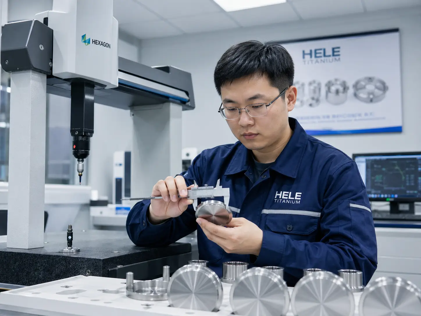
Create a characteristic-by-characteristic plan with method, fixture/preload, equipment, sampling, acceptance and report. Contact force, clamping and datum simulation can change the measured shape of thin diaphragms.
| Control point | Possible method when suitable | Buyer decision |
|---|---|---|
| Material identity | MTC, Grade/UNS/specification and heat/lot link | Incoming material matches the order |
| Thickness | Micrometer, non-contact or section method with defined locations | Incoming and/or formed requirement is met |
| Profile | Optical scan, comparator, CMM/non-contact metrology or controlled fixture | Free-state or fixtured geometry meets the approved definition |
| Edge and surface | Visual standard, magnification, burr/crack criteria and cleanliness method | Functional and joining surfaces are acceptable |
| Interface | Fixture, gauge or dimensional report | The component fits the approved assembly boundary |
12. Assign Complete-Assembly Performance Validation
Component conformity does not prove complete-system performance. The contract must state which party performs each validation, the test article, fixture, environment, procedure, sample size, limits, report and approval authority.
Frequency response, sensitivity, distortion, breakup behavior, power handling, environmental and life tests under the OEM method.
Span/sensitivity, linearity, hysteresis, repeatability, drift, temperature effects, overload and cycle stability.
Proof, burst, leak, vacuum, pressure cycling, temperature cycling, media compatibility and permanent-set limits.
Customer qualification, risk management, process validation, biocompatibility, sterilization and regulatory approval remain explicitly assigned.
13. Link Material, Tooling, Batch and Change Control
Define traceability from raw-material heat/lot through blank, forming batch, tool/revision, trimming, joining, inspection status, golden sample, packing and release documents. Record whether traceability is part-, batch- or shipment-level.
- Require written approval for Grade, thickness, source, condition, tool, route, setting, processor or inspection-method changes where qualification depends on them.
- Define revalidation after tool repair, relocation, long shutdown or significant batch drift.
- Control nonconformance, rework, repair, concession, retest and replacement.
- Do not treat ISO 9001 or another management-system certificate as finished-component performance evidence.
14. Protect Thin Components During Packing and Delivery
Thin diaphragms can be damaged by contact, vibration, stacking, humidity, particles or careless unpacking. Define individual nests, separators, trays, cavities, orientation, quantity per pack, clean bags, labels and outer protection as needed.
- Prevent dome/profile collapse and edge contact.
- Separate part numbers, revisions, lots and inspection status.
- Align inner label, outer label, packing list and certificate.
- Provide unpacking, handling and storage instructions where component shape or cleanliness is sensitive.
15. Normalize Cost and Quotation Scope
Cost may be driven by source material and thickness, tooling, forming trials, trim complexity, yield, prototype loops, profile inspection, golden-sample control, joining, validation, quantity, packing and logistics. Compare the same scope instead of unit price alone.
- Separate tooling, prototype, inspection/validation and recurring unit charges.
- State tool ownership, maintenance and replacement terms.
- Record MOQ driver, validity, schedule assumptions and exclusions.
- Make technical deviations visible beside the quoted requirement.
16. Complete Titanium Diaphragm Purchase Guard
16.1 Component identity and scope
- Name the diaphragm role and complete assembly.
- State formed component, joined subassembly or other delivered scope.
- List drawing/model/sample authority and revisions.
- Freeze buyer/supplier design and validation responsibility.
16.2 Material and thickness
- State Grade/UNS, material specification/revision and condition.
- Define nominal thickness, tolerance, locations and method.
- Separate incoming-stock and formed-part thickness requirements.
- Control heat/lot traceability and substitutions.
16.3 Geometry and interface
- Define overall/active diameter, height, radii, corrugation and sections.
- State free-state or fixtured measurement condition.
- Control tabs, holes, annulus, flange, clamp, bond or weld interfaces.
- Identify assembly datums and no-touch areas.
16.4 Service and load cases
- Provide acoustic, pressure, sensor or industrial duty.
- State normal, overload, vacuum, temperature, media and cycle conditions.
- Define expected travel/excursion and boundary support.
- List failure criteria and responsible approval authority.
16.5 Tooling and prototype control
- Define tool type, ownership, storage, maintenance and revision.
- Agree prototype quantity and inspection/assembly test plan.
- Control golden sample ID, limits, storage and use.
- Set production release and revalidation triggers.
16.6 Forming, trimming and secondary processes
- Review springback, thinning, wrinkling, tearing and residual stress.
- Define trim, burr, edge, cleaning and heat-treatment requirements.
- List external processors, specifications, certificates and change control.
- Prohibit unapproved repair or route substitution.
16.7 Component inspection
- For every characteristic state method, fixture, sampling, acceptance and report.
- Ensure measurement force and clamping do not distort the part.
- Define surface/edge visual standards and profile comparison.
- Link inspection results to material, tool and batch.
16.8 Assembly and functional validation
- Assign acoustic, sensor, pressure, leak, cycle and environmental tests.
- State procedure, test article, fixture, sample size, limits and report.
- Separate prototype qualification from routine lot acceptance.
- Keep device/regulatory approval with the responsible product owner.
16.9 Documents and commercial control
- Agree MTC, dimensional/profile report, process records, validation and CoC.
- Normalize quantity, currency, Incoterm, named place and required date.
- Separate tooling/prototype and recurring charges.
- Record exceptions, validity, MOQ and schedule assumptions.
16.10 Packing and delivery
- Prevent profile collapse, edge contact, contamination and lot mixing.
- Define nests, trays, separators, pack quantity and labels.
- Align part, package, packing list and document identity.
- State unpacking, handling and storage instructions where needed.
Red flags before purchase order
Audio, sensor, pressure and industrial functions are treated as interchangeable.
No controlled profile, master-sample plan or inspection method exists.
Post-forming distribution and measurement locations are not controlled.
Assembly, test procedure, fixture, environment and approval owner are missing.
Decision gate
Do not release the order until component role, product definition, material, thickness, profile, interfaces, tooling, inspection, validation, traceability, packing and commercial terms describe one verifiable deliverable.
17. RFQ and Pre-Order Checklist
Application, delivered scope, drawing/model/sample authority and revision.
Grade/UNS, specification, condition, thickness, tolerance, locations and method.
Diameter, profile, corrugation, edge, holes/tabs, support, bond or weld joint.
Tool status/ownership, prototype, forming, trimming, cleaning and external processes.
Component plan, golden sample, assembly tests, reports and approval authority.
Quantity, tooling/prototype cost, MOQ basis, packing, Incoterm and required date.
18. Titanium Diaphragm Purchasing FAQ
Is there one universal specification for every titanium diaphragm?
No. Audio domes, sensor membranes, pressure diaphragms and diaphragm-seal elements have different functional and validation requirements. The purchase order must identify the actual component role and applicable product or customer specification.
How should diaphragm thickness be specified?
State nominal thickness, tolerance, measurement locations and method, whether the requirement applies before or after forming, and any permitted thickness distribution. A raw-sheet certificate alone may not establish formed-part thickness.
How should a formed profile be accepted?
Use a controlled drawing or digital profile with datums, section locations, heights, radii, corrugation geometry and a defined optical, tactile or fixture-based measurement method. A visual match alone is not sufficient for critical geometry.
When is ASME B40.100 relevant?
It may be relevant when the ordered item is within its scope for pressure gauges or gauge attachments, including diaphragm seals. It is not a blanket standard for audio, sensor, pump, valve or other diaphragm components.
Can raw material certified to ASTM F67 or ISO 5832-2 be called an approved medical diaphragm?
No. Those material standards do not by themselves establish finished-device design, biocompatibility, manufacturing-process validation, sterilization or regulatory approval.
How should two diaphragm quotations be compared?
Normalize product role, drawing/sample revision, material and condition, thickness, formed profile, tooling, prototype approval, interfaces, joining, inspection, performance-validation boundary, documents, quantity, packing, Incoterm, schedule assumptions and exclusions.