Most CNC titanium quotation gaps begin with four choices: the starting material, the amount of metal that must be removed, the features that are difficult to support or reach, and the evidence required at delivery.
A useful purchase guide should help you make those choices—not turn your RFQ into a quality manual. Start with the surfaces and interfaces that make the part work. Keep tight controls there, and give the manufacturer room to use an efficient route on non-critical geometry.
The short answer: send the controlled drawing and model, but also identify the features that drive fit, sealing, motion or load. That context is what allows a machining supplier to distinguish a functional requirement from an expensive default.
Looking for drawing-based supply rather than general guidance? Review HELE custom CNC titanium parts and send the current files for a project-specific review.
1. What actually changes the price of a CNC titanium part?
Titanium stock is only one part of the quote. A simple component can become expensive when its geometry demands long-reach tooling, repeated setups, slow finish passes, dedicated gauges or extensive reporting. Two suppliers can therefore quote the same drawing on very different assumptions.
Large pockets, thick starting stock and an inefficient bar or plate size increase the amount of titanium bought and removed.
Features spread across several orientations need more handling and make datum transfer more important.
Deep pockets, narrow slots and small corner radii can require longer or smaller tools that cut less rigidly.
Tight fits and geometric controls may need dedicated finish passes, thermal stabilization and additional inspection.
Heat treatment, EDM, coating, polishing, cleaning and marking add handoffs, lead time and new acceptance points.
Material certificates, first-article reports, full dimensional data and special-process records should be priced as part of the scope.
A better comparison: ask each supplier to state the starting stock, included processes, inspection level, document package, exclusions and delivery basis. A lower unit price may simply describe a narrower job.
2. Choose the titanium grade and starting stock together
“Grade 5 titanium” does not fully define the order. The material specification, condition and product form determine what the mill cert covers and influence how much stock must be removed. The drawing may also require a particular route because of strength, section size, downstream qualification or customer approval.
| Starting form | Where it often fits | What to review before choosing it |
|---|---|---|
| Bar or billet | Turned parts, shafts, sleeves, pins and compact milled parts | Diameter or section availability, material yield, straightness, condition and heat/lot evidence |
| Plate | Brackets, discs, housings and broad prismatic parts | Thickness, flatness, cutting allowance, rolling direction where relevant and the amount of pocketing |
| Forging | Parts whose specification, section or manufacturing route calls for a forged preform | Forging design, qualification, heat treatment, machining allowance, lead time and ordered inspection |
ASTM B348/B348M, ASTM B265 and ASTM B381 address different titanium product forms. They help define the starting material; they do not replace the finished-part drawing, threads, surface requirements or final inspection.
3. Why titanium needs a different machining conversation
Titanium can be machined to precise results, but it does not release heat or resist tool pressure in the same way as many common shop materials. Its low thermal conductivity concentrates heat near the cutting edge. Its comparatively low elastic modulus allows slender or lightly supported features to deflect under load. Titanium can also smear or gall when tool condition, contact and lubrication are poorly controlled.
Tool condition, coolant delivery and uninterrupted cutting matter because excess heat can accelerate wear and change the finished surface.
A thin wall or slender shaft may deflect while being cut and spring back after the tool passes, causing taper, chatter or profile variation.
Thread form, mating material, surface condition and any approved lubricant or anti-galling treatment need to be considered together.
Technical basis: TIMET's titanium design and fabrication handbook identifies low thermal conductivity, reactivity with cutting tools and low elastic modulus as practical machining considerations. Exact speeds, feeds and tooling remain process- and alloy-specific.
4. Geometry is where the DFM savings usually begin
The best DFM change is rarely “loosen everything.” It is usually a small change to a non-critical feature that allows a stiffer tool, fewer setups or better support while preserving the functional interfaces.
Thin walls and slender features
Wall thickness by itself is not enough to predict difficulty. Unsupported height, wall length, pocket depth, stock condition and profile tolerance all matter. When a thin feature is essential, staged roughing and finishing, temporary support or a revised datum strategy may be needed.
Deep pockets and internal corners
A deeper pocket requires greater tool reach. A very small corner radius may force a smaller cutter, increasing deflection and cycle time. Use the largest internal radius the design can accept and identify which corner or floor actually performs a function.
Holes and inaccessible features
Long blind holes, intersecting passages and features hidden behind shoulders affect both machining and inspection. Through-holes and standard tool access are usually easier to control, but the final choice must follow the part's pressure, flow, assembly and cleaning needs.
Reduce avoidable setup changes
Features controlled to one another are easier to machine and inspect when they can remain in a stable setup. Where multiple setups are unavoidable, the datum scheme should reflect how the part will be transferred and measured.
5. Put tight requirements where they protect function
A blanket tight tolerance can add machining and inspection time without improving the assembly. A better drawing separates functional fits, sealing faces, alignment features and load paths from geometry that only clears another component.
| Feature | Useful information for review | Common source of avoidable cost or dispute |
|---|---|---|
| Bores and fits | Mating part, fit purpose, datum relationship, final finish and inspection method | A tight size tolerance with no control of position, form or surface |
| Internal threads | Thread system, size, pitch, class, engagement, lead-in, runout and gauge | Calling out thread depth without space for tool runout in a blind hole |
| Thin profiles | Free-state or restrained inspection, datum setup and functional surface | Applying the same profile tolerance to supported and unsupported regions |
| Surface texture | Required parameter, surface, direction where relevant and whether it applies before or after finishing | One roughness value copied onto every face, including non-functional areas |
| Edges and burrs | Critical edges, permitted break, sealing or flow function and inaccessible intersections | “Break all edges” changing a functional corner or thread entrance |
For an EDM feature, fatigue-sensitive surface or post-heat-treatment surface, the drawing should state the required condition and any removal or verification step. Terms such as “remove recast layer,” “remove alpha case” and “passivate” are not interchangeable.
6. Buy the inspection evidence that answers the real risk
A material certificate supports the identity and properties of the starting stock within its scope. It does not prove that the finished bore, thread, sealing face or profile is acceptable. Finished-part evidence must follow the characteristic.
Material test report or inspection certificate linked to the heat or lot, in the format required by the order.
Suitable gauges, CMM or other dimensional methods tied to the drawing, datum setup and sampling plan.
Thread gauges, surface-texture measurement and visual criteria where these are part of acceptance.
Process certificates and order-specific tests for heat treatment, coating, cleaning, NDT or other controlled operations.
A CMM report is useful for accessible dimensional and geometric characteristics, but it does not automatically prove thread form, surface texture, material chemistry, internal defects or cleanliness. First-article reporting is most valuable when its scope and approval role are agreed before production.
7. Match the part to HELE's machining and inspection route
Equipment matters when it answers a practical question: can the part be held rigidly, can the important features be reached in a stable setup, and can those features be measured in the same datum system used on the drawing? HELE's equipment list covers multi-axis milling, CNC turning, deep-hole work, grinding, wire cutting, waterjet cutting and dimensional or material checks.
| Machining or inspection route | Capacity shown in HELE's equipment list | What it can help the buyer evaluate |
|---|---|---|
| Five-axis machining | 700 × 600 × 500 mm and 1000 × 1150 × 1000 mm travels; selected equipment is listed at ±0.005 mm precision | Complex multi-face parts, angled features and fewer datum transfers where the geometry and fixture allow |
| Four- and three-axis machining | Four-axis travel of 1300 × 800 × 1000 mm, listed at ±0.005 mm; three-axis travel of 850 × 550 × 550 mm, listed at ±0.01 mm | Larger prismatic work, housings, brackets and parts whose main features suit a stable indexed or vertical setup |
| CNC turning | Machines with an 800 mm swing and turning diameters of 480 or 500 mm; larger CNC turning with a 1250 mm swing and turning diameter up to 880 mm | Shafts, sleeves, rings, discs and other rotational parts; the drawing still determines chucking, unsupported length and finished diameter limits |
| Deep-hole, boring and grinding | Listed drilling range of Ø20–Ø100 mm, boring range of Ø45–Ø360 mm and cylindrical grinding diameter up to Ø200 mm | Long bores, internal diameters and finishing routes that cannot be judged from overall part size alone |
| Wire cutting and waterjet cutting | Wire-cutting travel of 350 × 250 × 250 mm with a listed maximum workpiece size of 1030 × 800 × 350 mm; waterjet travel of 2000 × 4000 mm | Profiles, slots, cut blanks and features where a non-milling route may reduce stock removal or improve access |
| Inspection and material checks | CMM measuring travel of 1000 × 1200 × 800 mm, plus digital microscopy, handheld XRF screening, Rockwell hardness testing and ultrasonic flaw detection from 0.1 to 15 MHz | Matching the evidence to the risk: dimensions and geometry, visual detail, material screening, hardness or internal-discontinuity checks |
What the equipment figures mean: they establish the available machine envelope and a starting point for process planning. The ±0.005 mm values are specifications listed for selected machining centers—not a blanket tolerance for every finished part. HELE confirms finished-part capability by feature after reviewing the geometry, titanium grade and condition, setup, quantity, secondary processes and measurement method.
Inspection tools also have defined limits. Handheld XRF can support material screening, but it does not replace the ordered mill certificate or a required laboratory chemistry report. Ultrasonic testing is meaningful only when the applicable material, procedure, sensitivity, acceptance criteria and reporting scope are agreed.
Equipment basis: HELE machining and inspection equipment list. Part acceptance remains governed by the controlled drawing, agreed quotation and inspection plan.
A useful quotation review should leave you with four clear answers
- Material basis: which grade, specification, condition and starting form the quote uses.
- Manufacturing route: which machine class, setups and secondary processes the geometry requires, including any size or access constraint.
- Acceptance basis: which critical features will be checked, by what method and with what report.
- Commercial basis: quantity, one-time charges, assumptions, exceptions, packing and delivery target.
8. A shorter RFQ that still supports an accurate quote
2D drawing and 3D model, revision, units and which file controls if they conflict.
Titanium grade or UNS, material specification, condition, preferred starting form and certificate requirement.
Critical interfaces, datums, fits, sealing faces, threads, passages and any no-touch areas.
Surface texture, edge condition, cleaning, heat treatment, coating, marking and other secondary work.
Critical characteristics, sampling, first article, reports, traceability and any customer approval steps.
Prototype and production quantities, annual demand if known, destination, required date and packing needs.
Questions buyers often ask
What information is needed to quote a CNC titanium part?
Send the controlled drawing and model, revision, titanium grade and material specification, quantity, critical interfaces and tolerances, threads, surface requirements, secondary processes, inspection documents, packing and delivery target.
Why do two CNC titanium quotations differ so much?
Suppliers may have assumed different starting stock, material yield, setup count, machining time, tolerance scope, secondary processing, inspection, documentation or delivery responsibility. Compare the assumptions before comparing unit prices.
Does a material certificate prove that the finished part is acceptable?
No. It supports raw-material identity and properties within the certificate scope. Finished-part acceptance also depends on the drawing, dimensions, surface, threads, special processes and agreed inspection evidence.
What do the ±0.005 mm equipment figures mean?
They are specifications listed for selected multi-axis machining centers, not a universal finished-part tolerance. Finished-part capability depends on feature geometry, setup, titanium grade and condition, quantity, secondary processing and the agreed measurement method.
Technical references
- TIMET — Titanium Design and Fabrication Handbook
- ASTM — Current titanium and titanium-alloy standards
- ASME Y14.5 — Dimensioning and Tolerancing
- ISO 21920-1 — Surface texture indication
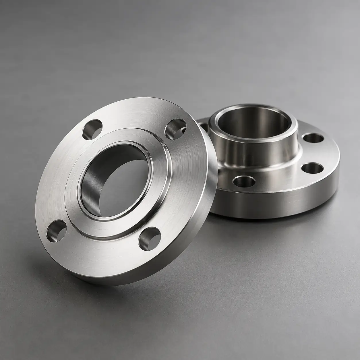
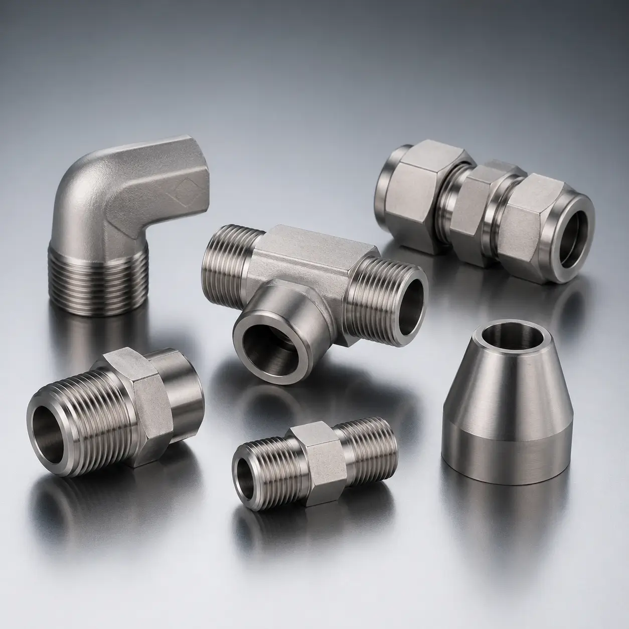
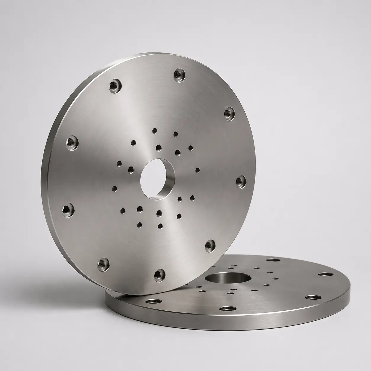
Examples of drawing-based titanium components
Images help describe the part family; the controlled drawing and quotation still define the deliverable.