
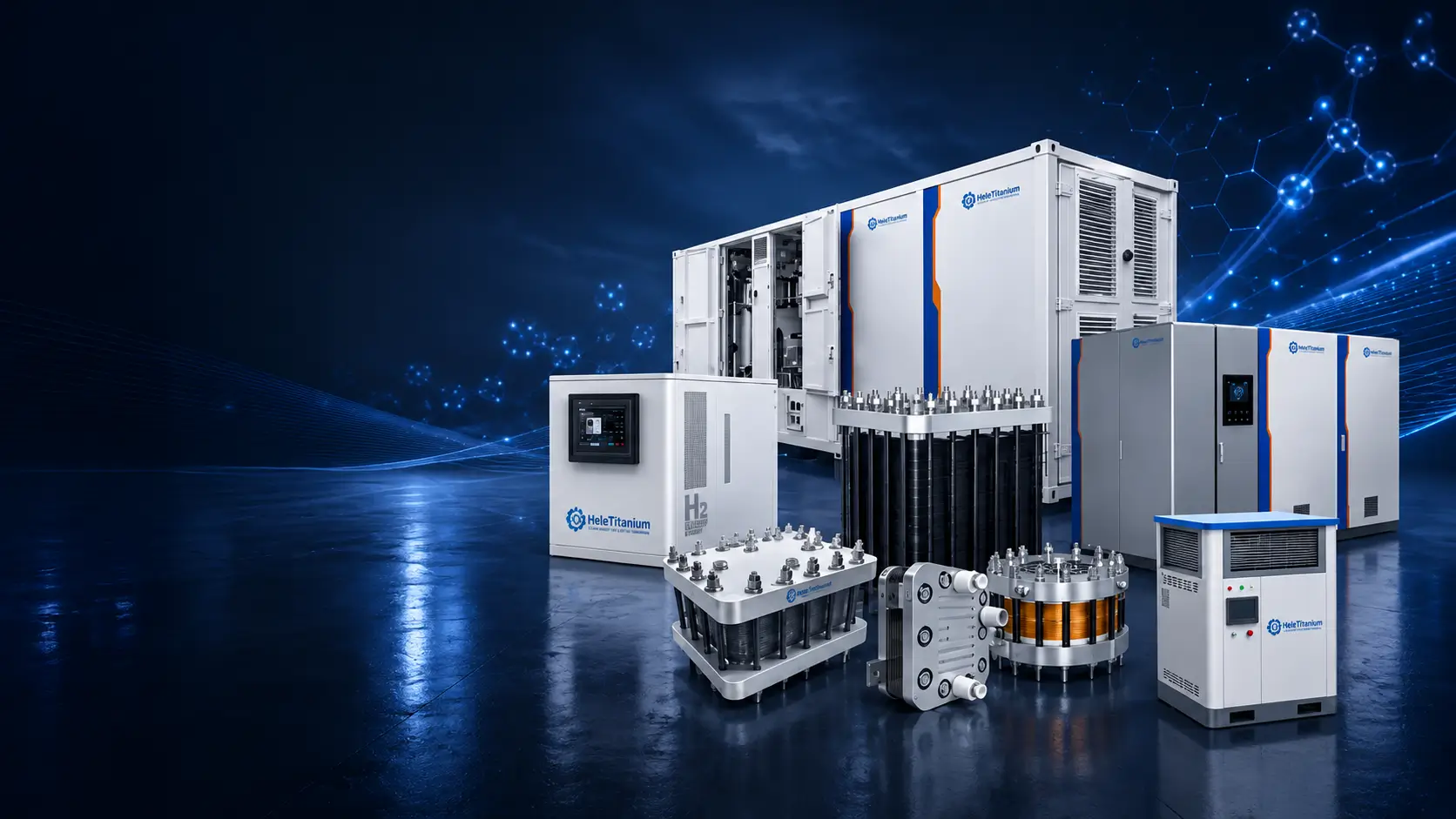
A detailed engineering and purchasing guide for defining PEM electrolyzer duty, comparing technologies and system configurations, reviewing stack and balance-of-plant quality, preparing FAT requirements and issuing a controlled RFQ.
1. The Critical Role of PEM Electrolyzers in Green Hydrogen Projects
A PEM electrolyzer purchase usually begins with a hydrogen target, but the equipment decision reaches much further than production rate. The selected system changes the electrical design, water-treatment duty, cooling load, gas-conditioning route, building or container layout, safety concept, control philosophy, maintenance plan and the evidence required at acceptance. If those items are considered only after a model has been chosen, the project often returns to the same questions during detailed engineering, when changes are slower and more expensive.
PEM technology is often considered where a compact installation, rapid response, high current density or operation with variable renewable power is important. Those characteristics do not make every PEM system suitable for every renewable profile. The stack, rectifier, thermal system, gas-liquid separation and control logic have to work together across startup, low load, ramping, standby and shutdown. A supplier should therefore review the time-based operating profile, not only the maximum electrical input or a single hydrogen-flow figure.
Start with the hydrogen service, not the equipment name
Describe where the hydrogen goes, how it will be used and what happens when production is interrupted. A laboratory may value clean gas at a stable low flow. A refueling project may be constrained by compressor and storage scheduling. An industrial user may care more about availability, redundancy and the tie-in pressure at an existing header. A power-to-gas project may need the system to follow a renewable-power profile without exposing the stack to an unsuitable number of starts, deep turndown events or thermal cycles.
| Project question | Why it changes the electrolyzer | What to record before RFQ |
|---|---|---|
| How much hydrogen is required? | It drives stack/module count, rectifier size, water use, cooling and gas handling. | Normal, minimum and peak flow; operating hours; annual demand; reference conditions. |
| Where is hydrogen handed over? | Pressure and quality depend on the measurement point and included conditioning equipment. | Delivery flange, sampling point, pressure, purity, dew point and impurity limits. |
| How will power vary? | Ramps, curtailment and cycling affect controls, temperature and degradation. | Power-duration data, ramp limits, starts/stops, standby strategy and grid requirements. |
| What must remain available? | Availability targets influence redundancy, isolation, spares and maintenance access. | Planned/unplanned outage basis, module isolation and required production during maintenance. |
| Who owns the site interfaces? | Unclear battery limits create gaps between the package, EPC and downstream equipment. | Utilities, piping, cabling, ventilation, permits, compression, storage and commissioning responsibility. |
Where PEM may—and may not—fit
A sound technology decision compares alternatives under the same hydrogen output, delivery pressure, gas quality, operating profile, site conditions and cost boundary. PEM can be attractive for compact and dynamic projects, but a stable base-load project may place greater weight on capital cost, established operating history or locally available service. High-temperature electrolysis may be relevant where suitable heat integration exists. AEM may be considered in development or selected commercial applications, but maturity, electrolyte management and supplier evidence need separate review.
Purchase implication: Do not ask suppliers to quote only 'a PEM electrolyzer of X MW.' Supply a hydrogen duty and responsibility boundary. Megawatts describe electrical scale; they do not by themselves define usable hydrogen, pressure, quality, availability or the equipment included.
Project definition checkpoint
- Hydrogen end use, delivery point and downstream equipment are identified.
- Normal, minimum, peak and annual production are stated in consistent units.
- The electrical profile includes ramping, curtailment, starts, stops and standby.
- Water source, cooling concept, ambient conditions and site limitations are known or marked open.
- The buyer, EPC, supplier and end user have named design and acceptance responsibilities.
2. What Is a PEM Electrolyzer?
A proton exchange membrane water electrolyzer uses direct current to split water into hydrogen and oxygen. The membrane conducts protons between the electrodes while helping keep the product gases separated. In a commercial installation, however, the electrochemical stack is only one part of the equipment needed to deliver controlled hydrogen. Water preparation, circulation, power conversion, cooling, gas-liquid separation, gas conditioning, instrumentation, controls and safety functions determine whether the stack can operate within its intended window.
This distinction matters in purchasing because the same phrase—PEM electrolyzer—may be used for a bare stack, an electrolysis module, a laboratory generator, a skid-mounted package or a containerized production system. Two quotations can therefore show the same nominal output while including very different equipment and responsibilities. A lower-priced offer may exclude the rectifier, water treatment, dryer, chiller, gas analysis, ventilation, installation or commissioning. The difference is not visible until the battery limits are compared line by line.
| Term | Usually includes | Usually does not establish by itself | Buyer action |
|---|---|---|---|
| PEM cell | One electrochemical repeating unit. | System output, delivered purity, controls or site safety. | Use for material and electrochemical development discussions. |
| PEM stack | Multiple cells, compression structure, manifolds and electrical/fluid interfaces. | AC energy, drying, final delivery pressure or complete-system compliance. | Freeze stack revision, test conditions and OEM interfaces. |
| Electrolysis module | Stack plus selected local piping, sensors or support functions. | A consistent scope across suppliers. | Request an equipment list and interface drawing. |
| Complete electrolyzer system | Stack and defined balance of plant, controls and package integration. | Compression, storage, building works or EPC scope unless stated. | Mark every included, optional and customer-supplied item. |
| Hydrogen generator | A packaged appliance or system intended to generate hydrogen. | The precise project battery limits or certification status. | Confirm configuration, jurisdiction and applicable safety route. |
What the nameplate should tell you
A useful nameplate or approved datasheet links the model and serial number to rated electrical conditions, design and operating pressures, temperature limits, permitted water specification, production basis and applicable documentation. It should also make clear whether hydrogen flow is quoted at normal conditions, standard conditions or another reference. Without that basis, a volume-flow figure cannot be compared accurately.
Purity and dew point also need a location. Gas leaving the separator is not the same commercial product as gas leaving a dryer or purification train. Similarly, stack DC consumption is not complete-system AC consumption. Pumps, controls, cooling, heaters, drying and other auxiliaries can materially change the boundary. The buyer should insist that each performance value names the equipment configuration and measurement point behind it.
A practical scope statement
A clear RFQ can say: 'Supply a PEM water-electrolysis system delivering hydrogen at the defined battery limit, including the equipment listed in the scope table, tested under the agreed utilities and operating profile.' This wording is more useful than asking for a 'turnkey unit' because turnkey can mean different things to the equipment supplier, EPC contractor and end user.
Do not assume: A stack datasheet is not a complete-system guarantee, and a system brochure is not an order-specific datasheet. The quotation, approved equipment list, drawings, test procedure and exceptions should describe the same deliverable.
3. How PEM Water Electrolysis Works
Inside the cell, water is supplied to the anode side. Under direct current, the oxygen-evolution reaction produces oxygen, protons and electrons. The membrane conducts the protons to the cathode side, while electrons travel through the external circuit. At the cathode, protons and electrons combine to form hydrogen. Cells are connected in series so that stack voltage rises with cell count, while the hydrogen-production rate is closely related to current and Faradaic efficiency under the stated operating conditions.
That short description is chemically correct but incomplete for procurement. The stack must receive water of suitable quality and flow, operate within temperature and pressure limits, remove heat, separate gas from circulating water, control differential pressure and respond safely to off-normal conditions. Startup and shutdown also matter. Before hydrogen is released to use or storage, the system may need purging, stabilization and verification that gas quality is within the agreed limit.
| Operating stage | What happens | What the buyer should verify |
|---|---|---|
| Water preparation | Source water is treated and monitored before it reaches sensitive wetted components. | Water specification, treatment scope, storage, sampling point, alarms and consumables. |
| Power conversion | AC power is transformed or rectified to the DC window required by the stack. | Input standard, rectifier efficiency, harmonics, power factor, protection and DC control range. |
| Electrochemical conversion | Current passes through the cells and water is converted to hydrogen and oxygen. | Current density basis, voltage limits, temperature, pressure and permitted operating envelope. |
| Gas-liquid separation | Generated gases are separated from circulating water. | Separator design conditions, level control, carryover, drainage and crossover monitoring. |
| Gas conditioning | Drying or purification may be used to reach a delivery specification. | Included equipment, sampling location, regeneration, off-spec routing and replacement media. |
| Delivery and shutdown | Gas is sent to the downstream user or isolated; the system enters standby or safe shutdown. | Battery-limit pressure, valves, vent/relief route, purge method, interlocks and restart conditions. |
Why low-load and dynamic operation need separate review
Renewable integration is often described as a general PEM advantage, but the acceptable operating envelope belongs to the complete design. At low current, crossover and gas-quality behavior may change. During rapid load movement, the stack, rectifier, water circulation and thermal controls may respond at different rates. Frequent cold starts, hot standby and shutdowns can create a different degradation pattern from continuous operation. The RFQ should therefore include the expected time at each load range, not only a desired turndown percentage.
Why water quality is an operating control
Water quality should not be reduced to a single conductivity number copied from a brochure. The supplier should state the required inlet specification, monitoring method, alarm and shutdown values, sampling location and response to an excursion. The treatment train must be selected from the actual source-water analysis. A laboratory DI source, municipal water and reused process-water stream present different risks and pretreatment needs.
What to request with performance data
- Stack or system configuration and build revision used for the test.
- Water quality, inlet temperature, flow, operating temperature and pressure.
- Current, voltage, current-density denominator and stabilization time.
- Hydrogen measurement method, reference conditions and sampling point.
- Gas-conditioning status and analytical instrument/calibration information.
- Whether the reported energy is stack DC, rectifier DC input or complete-system AC input.
- Test duration, beginning/end state, interruptions and treatment of auxiliary loads.
Comparison rule: If two suppliers use different gas reference conditions, electrical boundaries or conditioning equipment, their output and energy figures are not directly comparable. Normalize the method before comparing the number.
4. Main Components of a PEM Electrolyzer
A PEM electrolyzer is a chain of interdependent components rather than a single machine with one decisive part. A high-quality membrane cannot compensate for unsuitable water, poor compression, nonuniform current distribution or an undersized cooling loop. Procurement should therefore examine the stack bill of materials and the system equipment list together, while respecting legitimate supplier intellectual property.
| Component | Function | What changes performance or risk | Useful procurement evidence |
|---|---|---|---|
| MEA / catalyst-coated membrane | Provides the electrochemical reaction area and proton-conducting path. | Active area, catalyst system, coating consistency, membrane handling and operating window. | Controlled specification, build revision, incoming/production controls and qualification basis. |
| Porous transport / current-collection layers | Distribute water and gases and conduct current at the electrode interfaces. | Porosity, thickness, coating/contact resistance, cleanliness and compression. | Material specification, dimensional inspection and controlled source/change process. |
| Bipolar or flow-field plates | Distribute fluids, connect cells electrically and help define the pressure boundary. | Material, coating, channel geometry, flatness, corrosion/contact behavior and machining quality. | Drawing revision, material/coating evidence and dimensional/visual inspection. |
| Seals and frames | Separate fluids and maintain internal/external leak tightness. | Material compatibility, groove design, compression, temperature, pressure and storage history. | Approved material, lot/expiry control, assembly method and leak-test record. |
| End plates and compression hardware | Maintain stack compression and mechanical alignment. | Load distribution, stiffness, tie-rod/fastener control, insulation and transport restraint. | Assembly procedure, torque/load record, dimensional inspection and handling instructions. |
| Rectifier / DC supply | Provides controlled current and voltage to the stack. | Efficiency, ripple, dynamic response, harmonics, cooling, protection and communication. | Electrical datasheet, single-line diagram, protection settings and FAT measurements. |
| Water loop | Treats, stores, circulates and monitors water supplied to the stack. | Source water, treatment capacity, wetted materials, temperature, flow, filtration and monitoring. | P&ID, water specification, instrument list and commissioning procedure. |
| Gas separation and conditioning | Separates water and, where included, dries or purifies product gas. | Pressure, carryover, load range, regeneration, sampling and off-spec routing. | Equipment datasheets, P&ID, analytical method and performance-test boundary. |
| Cooling system | Removes stack, rectifier and auxiliary heat. | Design ambient, coolant, approach temperature, turndown, redundancy and fouling. | Heat balance, cooler/chiller datasheet, utility requirement and control sequence. |
| PLC, HMI and safety instrumentation | Controls operation, records data and moves the package to a safe state. | Sensor range/accuracy, voting, alarm limits, software version, access and fail-safe behavior. | I/O list, cause-and-effect, alarm matrix, functional test and backup procedure. |
How far should a buyer investigate materials?
The buyer does not need the supplier's confidential formulation to write a controlled purchase specification. Instead, define measurable requirements: operating environment, electrical and pressure limits, chemical compatibility, traceability level, prohibited substitutions and the evidence needed if a source or material changes. For critical parts, the order can require notification and approval before a material, process or source change is introduced.
Component quality is not the same as system suitability
A certificate for an individual material does not demonstrate stack performance, and a stack performance test does not validate the complete gas-conditioning or control system. Evidence should follow the hierarchy of the product: material and component records, stack assembly and test records, system integration records, and finally the FAT for the supplied configuration.
Component review questions
- Which component specifications and sources are controlled for the ordered build?
- Which substitutions require customer approval, and how are revisions recorded?
- What cleanliness, handling, storage and shelf-life controls apply?
- How are assembly compression, alignment and sealing controlled?
- Which records are supplied with the equipment and which remain internal manufacturing records?
- What spare parts and consumables should be stored at site, and under what conditions?
5. Key Electrolyzer Technologies for Modern Hydrogen Production
Technology selection should be made before a detailed PEM RFQ is issued. All water-electrolysis technologies produce hydrogen from water and electricity, but they differ in electrolyte, temperature, materials, dynamic behavior, footprint, system complexity, commercial maturity and the way they interact with the project. A comparison is only fair when every option is evaluated at the same hydrogen delivery point and includes the equipment required to meet that point.
| Technology | Typical operating concept | Potential project strengths | Questions that need evidence |
|---|---|---|---|
| PEM | Solid polymer electrolyte; low-temperature operation; compact stack architecture. | Dynamic operation, compact footprint and pressurized hydrogen capability may suit renewable and distributed projects. | Water-quality requirements, PGM/catalyst strategy, pressure/crossover limits, degradation under the real duty cycle and replacement plan. |
| Alkaline | Liquid alkaline electrolyte with established large-scale operating history. | May suit stable, large production duties where maturity and capital-cost structure are central. | Electrolyte handling, footprint, minimum load, gas quality, pressure route and dynamic-operation evidence. |
| AEM | Anion-conducting membrane, often with alkaline water/electrolyte conditions depending on design. | Development aims may include lower-cost material pathways and flexible architectures. | Commercial maturity, electrolyte/water specification, membrane durability, stack scale and field evidence. |
| SOEC | High-temperature steam electrolysis using a solid oxide electrolyte. | Can benefit from suitable steam and heat integration in industrial settings. | Heat source, thermal cycling, startup time, materials durability, steam quality and system integration. |
Avoid technology comparisons built from brochure maxima
One supplier may quote stack DC efficiency at a nominal point; another may quote complete-system AC consumption over a wider load range. One may include drying and cooling; another may stop at wet hydrogen leaving a separator. Even capital cost can be misleading if installation, power conversion, water treatment, compression, commissioning or replacement reserves are treated differently. Build a common battery limit before ranking technologies.
Questions for renewable-power projects
- What power-duration curve and curtailment behavior has been used for sizing?
- What is the permitted warm and cold start frequency, and how long does each state transition take?
- Which equipment limits ramp rate or minimum stable operation: stack, rectifier, thermal system or gas conditioning?
- How are gas quality and crossover controlled during low-load and transient periods?
- What standby modes consume power or water, and when is a purge required?
- How is degradation evaluated under the actual cycle rather than a steady laboratory point?
Decision method
Shortlist the technology only after defining five items: usable hydrogen specification, operating profile, site and utility conditions, safety/permitting route and lifecycle service plan. Then ask each supplier to state assumptions and exceptions against the same basis. The result may confirm PEM, or it may show that another technology is better for a stable or heat-integrated duty. The purpose of the comparison is not to prove that one technology is universally superior; it is to prevent a mismatch between the project and the equipment.
HELE scope note: This guide focuses on PEM water electrolysis. Technology comparisons provide selection context; they are not performance guarantees for an HELE configuration and do not replace project-specific engineering review.
6. What Is Inside a Complete PEM Electrolyzer System?
A complete system brings the electrochemical stack into a controlled production process. The practical question is not whether a brochure shows a pump, separator or PLC, but whether that item is included in the quoted price, sized for the selected duty, connected inside the supplier's battery limits and covered by the agreed test. A disciplined equipment list and P&ID are therefore more valuable than a generic statement that the package includes 'all balance of plant.'
| Subsystem | Typical duties | Scope questions for the quotation | Acceptance evidence |
|---|---|---|---|
| Stack/module | Converts water and DC electricity to hydrogen and oxygen. | Model/revision, module count, pressure arrangement, isolation and replacement boundary. | Stack test data, build identification and approved interfaces. |
| Power conversion | Transforms and rectifies incoming power and controls stack current. | Transformer, rectifier, switchgear, harmonics, power factor, protection, cooling and metering. | Electrical checks, protection test and measured power at agreed points. |
| Water treatment and circulation | Prepares, stores, circulates and monitors stack feed water. | Source analysis, pretreatment, polishing, tanks, pumps, filters, instruments and drains. | Water-quality verification, flow/control function and commissioning record. |
| Gas-liquid separation | Separates product gases from circulating water. | Design/operating pressure, level control, carryover, return path, drains and materials. | Pressure/leak and functional test under the agreed boundary. |
| Drying/purification | Conditions hydrogen to the delivery specification where included. | Technology, capacity, regeneration, startup time, turndown, consumables and off-spec handling. | Purity/dew-point test at the named outlet and analytical method. |
| Cooling | Rejects stack, rectifier and process heat. | Chiller, cooler or customer water; design ambient; redundancy; coolant and controls. | Heat-load basis, temperature-control demonstration and utility data. |
| Controls and safety | Sequences the system, records data and initiates alarms or shutdowns. | PLC/HMI, I/O, communications, remote access, detector/relief interfaces and E-stop scope. | Cause-and-effect, interlock, alarm, shutdown and recovery test. |
| Package/enclosure | Provides mechanical integration, access and environmental protection. | Skid/container, ventilation, lighting, heating, drainage, lifting, fire/gas system and site tie-ins. | GA inspection, ventilation/control test and packing/release record. |
Draw the battery limits
Mark the water inlet, electrical incomer, cooling connection, hydrogen outlet, oxygen outlet or vent, drains, relief/vent headers, instrument-air connection, network connection and foundation interface. For each boundary, state size, rating, quality, pressure, temperature, flow direction and the party responsible for mating equipment. The same drawing should show where supplier performance ends and downstream compression, storage or process use begins.
Package, skid and container are not equivalent
A skid may be intended for installation inside a suitable building. A containerized package may add enclosure, ventilation, gas detection, thermal control and weather protection, but its suitability still depends on ambient conditions, wind/snow/seismic loads, hazardous-area decisions, safe vent routing and maintenance access. Ask whether the container is a transport enclosure, an operating enclosure or both, and which site approvals remain with the buyer.
Build a responsibility matrix
| Work item | Supplier | Buyer/EPC | Joint hold point |
|---|---|---|---|
| Process design basis | State package assumptions and limits. | Provide duty, site and downstream requirements. | Approve design basis and battery limits. |
| Site utilities | Issue quality and capacity requirements. | Design and supply utility systems to the boundary. | Verify readiness before commissioning. |
| Safety review | Provide package hazards, safeguards and data. | Integrate into site HAZID/HAZOP and emergency plan. | Close interface actions. |
| FAT and commissioning | Execute agreed factory tests and provide procedures. | Witness as agreed and prepare site. | Accept results, deviations and retest plan. |
| Performance acceptance | Demonstrate the contracted boundary. | Provide compliant utilities and calibrated downstream measurement where assigned. | Approve method, data and exceptions. |
Common scope gap: Compression and storage are often outside the electrolyzer package. Never infer final delivery pressure from stack pressure capability. Name the pressure at each interface and identify every compressor, regulator and vessel in the supply boundary.
7. HELE Titanium PEM Electrolyzer Series Comparison
HELE's S, H, C and M families, together with containerized configurations, provide a useful first routing method. They should be treated as configuration directions rather than self-selecting catalogue products. The final model and equipment scope have to be reviewed against the hydrogen service, operating profile and site. This prevents a familiar problem: selecting a system from a headline flow value and discovering later that the required pressure, dryer, cooling arrangement, control interface or outdoor package was not included.
| Configuration direction | Good starting point when | Key engineering review | Do not assume |
|---|---|---|---|
| S-Series compact system | The project is laboratory, research, validation or small pilot duty. | Low-flow control, gas sampling, safe ventilation, data acquisition, utilities and scale-up intent. | That laboratory gas quality or controls automatically transfer to a larger system. |
| H-Series mid-range system | The project is distributed production, OEM integration or pilot scale-up. | Duty cycle, skid interfaces, rectifier, water/cooling, communications and FAT scope. | That a nominal output defines the complete delivery package. |
| C-Series industrial system | The project requires industrial on-site production and coordinated BoP. | Availability, redundancy, gas conditioning, maintenance isolation, site utilities and documentation. | That industrial use alone defines the applicable code or certification route. |
| M-Series modular system | Higher capacity is achieved through coordinated modules and shared or distributed BoP. | Module count, common-mode failures, electrical architecture, controls, layout, spares and phased expansion. | That simple multiplication of one module guarantees plant-level output or availability. |
| Containerized system | Outdoor, remote or packaged installation is preferred. | Ambient limits, enclosure rating, ventilation, detection, heat rejection, access, lifting and safe vent routing. | That the container removes the need for site permitting or hazardous-area review. |
A better way to request a recommendation
Send a one-page design basis before asking for a model. It should contain the hydrogen flow and reference conditions, normal and peak operation, pressure and gas quality at the delivery point, electrical source, source-water analysis, cooling utility, ambient range, installation type, downstream compression/storage, required standards, FAT expectations and planned schedule. If information is not yet known, mark it as an open item rather than replacing it with a guessed value.
How the series decision should be documented
- Selected configuration direction and the alternatives considered.
- Hydrogen, power, water, cooling and gas-delivery design basis.
- Included stack/module count and balance-of-plant architecture.
- Normal, minimum and peak operating points plus the permitted transient envelope.
- Customer-supplied utilities and downstream equipment.
- FAT boundary, witnessed tests, analytical methods and required documents.
- Options, exclusions and open engineering items with owners and due dates.
HELE should confirm current model availability and order-specific data before publication or quotation. A historical reference configuration, including any CH-series example, should not be presented as a current guaranteed model until its build revision, test basis and supply status have been checked.
Selection outcome: The customer should leave this step with an approved configuration basis, not merely a family name. The family routes engineering; the approved datasheet and scope define the order.
8. How to Evaluate PEM Stack Quality Inside a System Purchase
The stack deserves close review because it is the electrochemical core and a major lifecycle item, but quality cannot be judged from appearance, catalyst marketing or a single polarization curve. A credible evaluation connects the ordered build revision to controlled components, assembly records, leak and pressure evidence, electrochemical test conditions and a service plan. The buyer should also distinguish information required for acceptance from proprietary design information that is not necessary to verify performance.
| Quality area | What to examine | Evidence that is more useful than a claim |
|---|---|---|
| Configuration identity | Active area convention, cell count, stack revision, pressure arrangement and interfaces. | Approved GA/ICD, datasheet, serial/build identification and change record. |
| Component control | MEA-related specification, PTL/current collector, plates/coatings, seals and compression hardware. | Controlled BOM/specifications, approved sources, incoming checks and substitution control. |
| Assembly control | Cleanliness, alignment, compression, torque/load application, seal handling and in-process inspection. | Assembly traveler, inspection points, tool/calibration controls and nonconformance disposition. |
| Pressure integrity | External leakage, internal communication, test boundary and differential pressure. | Procedure with medium, pressure, duration, temperature, instrument and acceptance. |
| Electrochemical performance | Voltage/current behavior, temperature, pressure, flow, water and stabilization. | Raw and processed test data tied to the same stack and stated operating conditions. |
| Gas behavior | Crossover indicators and gas analysis across the required operating range. | Sampling point, analyzer type/range, calibration and low-load/high-pressure test basis. |
| Durability basis | Duty cycle, cycling, degradation calculation, end-of-life definition and maintenance. | Test duration, interruptions, beginning/end comparison and limits of extrapolation. |
| Release and traceability | Build records, deviations, software/test versions, packing and preservation. | Release dossier or manufacturing data record defined in the purchase order. |
Interpret performance curves carefully
A polarization curve is useful only when current density, cell/stack voltage, temperature, pressure, water flow and conditioning are known. It may show performance at the beginning of life rather than after prolonged operation. A supplier comparison should use matched conditions or clearly explain the conversion. If a curve is based on a single cell or short stack, ask how it relates to the production stack and which scale-up assumptions remain.
Define life before discussing lifetime
Lifetime is not a self-explanatory number. The order should define the operating profile, beginning-of-life condition, degradation metric, end-of-life threshold, data exclusions, permitted maintenance and responsibility for operation outside limits. DOE targets can provide development context, but they are guideposts and require performance, durability and cost targets to be met on the same relevant stack or system; they are not supplier guarantees.
Ask how the stack interacts with the system
Water contamination, rectifier ripple, thermal excursions, differential pressure, unsuitable purging or controls can damage a sound stack. Conversely, a stack issue can appear as a system symptom. Warranty and troubleshooting procedures should therefore specify what operating data must be retained, how alarms are exported, how remote support is handled and how responsibility is assigned between the stack supplier, system integrator and operator.
Stack evidence requested before release
- Approved stack datasheet, interface drawing and build revision.
- Defined pressure/leak-test procedure and result.
- Electrochemical/performance test conditions and result for the ordered or representative configuration.
- Gas/crossover evidence where required by the operating envelope.
- Traceability and release records at the level agreed in the ITP.
- Storage, installation, startup, operating and shutdown limits.
- Recommended spares, replacement method and warranty evidence requirements.
9. PEM Electrolyzers for Real-World Hydrogen Applications
Application labels are useful for routing an inquiry, but they do not define the equipment. A refueling project, industrial process and laboratory may all request high-purity hydrogen, yet their flow profile, pressure route, redundancy, analytical requirements and consequences of interruption differ. The application section of an RFQ should translate the end use into measurable operating and interface requirements.
Renewable-energy integration
Provide the expected electrical profile at a useful time resolution rather than stating only solar or wind capacity. Identify whether a grid connection, battery or power-management system smooths the input. Define permitted curtailment, minimum operating periods, ramping, starts/stops, hot and cold standby, and the production target over a day or year. Ask the supplier to explain which limitations arise from the stack and which arise from the rectifier, thermal system, separators, dryers or controls.
Industrial on-site hydrogen
Map the existing hydrogen header or process user. State normal and peak consumption, delivery pressure, purity and contaminants, permissible interruption, buffer storage, downstream regulation and process safety requirements. For a retrofit, supply site utility data and tie-in drawings. Availability may depend more on redundancy, isolation, spare parts and maintenance access than on the rated output of one stack.
Hydrogen refueling support
Separate generation from drying, compression, storage, precooling and dispensing. The electrolyzer outlet pressure is not the vehicle-fueling pressure. The project model should coordinate daily demand, station peaks, storage capacity, compressor duty, gas-quality standard and maintenance windows. Name the party responsible for the interface between the electrolyzer and refueling equipment.
Research, laboratory and test systems
Small systems still require safe ventilation, gas detection or appropriate monitoring, controlled exhaust/vent routing and suitable electrical installation. Define whether the purpose is hydrogen supply, component testing, renewable-profile emulation or stack research. Required data channels, sampling points, remote control, calibration, low-flow stability and access for experimental changes may matter more than maximum capacity.
Power-to-gas and chemical projects
For ammonia, methanol, synthetic fuels or gas-grid applications, coordinate the hydrogen specification and production dynamics with the downstream process. Determine whether oxygen is a by-product to be vented, monitored or recovered. Compression, storage and process-buffer design should be considered with the electrolyzer operating profile rather than treated as independent packages.
| Application | First data to provide | Typical hidden scope gap |
|---|---|---|
| Renewable hydrogen | Power-duration curve, cycling, annual target, grid/battery interface. | Assuming the stack alone determines ramp and turndown. |
| Industrial supply | Header pressure/quality, demand profile, availability and tie-in. | No isolation, buffer or maintenance production plan. |
| Refueling support | Daily demand, storage/compressor strategy and gas-quality route. | Confusing electrolyzer outlet pressure with dispensing pressure. |
| Laboratory/test | Purpose, flow stability, data acquisition, ventilation and sampling. | Treating a small hydrogen flow as a small safety responsibility. |
| Chemical/power-to-gas | Downstream process dynamics, contaminants, storage and oxygen plan. | Unassigned compression or process-buffer responsibility. |
Application rule: Use the application to explain the duty, not as a shortcut for selecting a grade or model. The same application name can require a different system when pressure, climate, operating profile or downstream equipment changes.
10. Custom PEM Electrolyzer Engineering Requirements
Customization should start with a user requirement specification and an interface list. Without those documents, custom engineering can become a sequence of isolated changes—a different pressure here, a new enclosure there—without checking the effect on stack duty, heat rejection, controls, safety or test scope. A controlled project moves from design basis to review, approval, manufacture, test and release with named revisions.
| Engineering stage | Main output | Buyer decision or hold point |
|---|---|---|
| Requirement definition | URS/design basis, operating profile, site data and battery limits. | Confirm assumptions, open items and responsible parties. |
| Concept selection | Configuration, stack/module count, preliminary PFD, layout and utility estimate. | Select the concept and record rejected alternatives. |
| Basic engineering | P&ID, equipment list, control philosophy, heat/material balance and interface schedule. | Approve process and safety basis before detailed manufacture. |
| Detailed engineering | GA, fabrication/electrical drawings, I/O, cause-and-effect, datasheets and ITP/FAT. | Freeze interfaces, document revisions and acceptance methods. |
| Manufacture and integration | Controlled build, inspections, nonconformance/change records and readiness review. | Witness hold points and approve material changes or deviations. |
| FAT and release | Executed procedures, raw/results data, punch list, documents, preservation and packing. | Accept, conditionally accept or require retest against agreed criteria. |
| Site completion | Installation checks, commissioning, training, SAT/performance acceptance and handover. | Close interface and documentation items before final acceptance. |
Pressure and gas-quality customization
State the required pressure at the delivery flange and the range during normal, startup, standby and upset operation. Identify whether pressure is produced electrochemically, controlled after separation or increased by downstream compression. For purity and dew point, specify the sampling point, analytical method, conditioning equipment and treatment of off-spec gas. Do not apply a purity number from a fully conditioned package to a bare stack or wet-gas outlet.
Electrical and control integration
Provide the site voltage/frequency, short-circuit and earthing information, power-quality limits and renewable or EMS interface. Define required communication protocols, commands, permissives, data tags, remote access and cybersecurity responsibilities. The cause-and-effect should describe how the package responds to water, temperature, pressure, gas detection, ventilation, electrical and communication faults.
Standards and certification
Create a standards register rather than listing well-known codes without context. ISO 22734-1:2025 addresses safety requirements for hydrogen generators using water electrolysis, but applicability, national adoption, certification route and the precise configuration covered must be established for the project. Pressure equipment, electrical, hazardous-area, machinery, building and local fire requirements may add separate obligations.
Change control after design freeze
Custom projects continue to evolve, but every change should identify its reason, affected documents, technical impact, schedule/cost effect and required requalification or retest. Changes to the stack, rectifier, pressure boundary, water specification, gas-conditioning train or safety logic should not be accepted through an informal email alone.
Documents to freeze before manufacture
- Approved design basis and responsibility matrix.
- PFD/P&ID, equipment list and battery-limit schedule.
- General arrangement, lifting/foundation and service-clearance requirements.
- Electrical single-line, load list and communication/I/O requirements.
- Control philosophy, alarm matrix and cause-and-effect.
- Applicable standards register and project safety actions.
- Inspection and test plan, FAT procedure and documentation index.
11. Installation, Commissioning and Maintenance
A successful FAT does not guarantee a successful site startup. Factory tests use defined utilities, temporary connections and controlled conditions; the site introduces actual electrical quality, water source, cooling system, piping cleanliness, ventilation, network integration and downstream equipment. Installation and commissioning responsibilities should be agreed before shipment so that site problems are not discovered during the supplier's mobilization.
Site readiness before delivery
- Foundation, access route, lifting plan, floor loading and maintenance clearances are approved.
- Electrical supply, earthing, harmonics/power-quality responsibilities and emergency isolation are ready.
- Water analysis and treatment capacity meet the approved specification; flushing and cleanliness are controlled.
- Cooling capacity, temperature, pressure, flow and water quality are available at the battery limit.
- Hydrogen, oxygen/vent, drain and relief routes are installed, cleaned and tested as required.
- Ventilation, gas detection, fire/safety interfaces and hazardous-area decisions are complete.
- PLC/EMS/network interfaces, tag lists and remote-access rules have been tested or simulated.
Commissioning sequence
Commissioning should progress from visual and document verification to utilities, leak/pressure checks, water treatment and circulation, instrument calibration, electrical energization, dry functional tests, controlled startup, gas handling and performance verification. Record the initial stack and system baseline—cell/stack voltage, current, temperatures, pressures, water quality, flow, gas quality and auxiliary loads—so later troubleshooting has a valid reference.
| Commissioning gate | Typical checks | Record retained |
|---|---|---|
| Mechanical completion | Installation, supports, piping, valves, vents, labels, access and preservation removal. | Mechanical completion checklist and punch list. |
| Utilities ready | Electrical, water, cooling, instrument air/network and downstream boundary. | Utility readings and readiness sign-off. |
| Safety ready | Detection, ventilation, interlocks, E-stop, relief/vent and emergency response. | Cause-and-effect and functional-test result. |
| Controlled startup | Purge, water circulation, pressure control, rectifier sequence and gas routing. | Startup log, alarms/deviations and corrective actions. |
| Performance acceptance | Output, energy boundary, pressure, gas quality, turndown or agreed operating points. | Raw data, calculations, calibration and signed acceptance. |
Maintenance planning
The maintenance plan should separate routine inspection, condition-based tasks, scheduled consumable replacement and major stack or subsystem service. Filters, polishing media, dryer components, pump seals, valves, analyzers, sensors and cooling equipment may have different service intervals. Ask which tasks can be performed by site personnel, which require supplier attendance and what evidence is needed to keep the warranty valid.
Operating data and troubleshooting
Trend water conductivity or other specified quality indicators, stack current and voltage, cell-voltage information where provided, temperatures, pressure differential, hydrogen output, gas analysis, alarms, starts/stops and auxiliary loads. When performance changes, preserve the data before changing setpoints or opening the stack. First confirm the measurement instruments and BoP—water, rectifier, cooling, pressure control and gas conditioning—before assigning the cause to the electrochemical core.
Recommended handover package
- Approved as-built drawings, datasheets and software/configuration versions.
- Operating, startup, shutdown, emergency and preservation procedures.
- FAT/SAT results, calibration records and baseline operating data.
- Preventive-maintenance schedule, consumables and recommended spares.
- Training record and authorized-support contacts.
- Warranty conditions, data-retention requirements and escalation route.
12. PEM Electrolyzer RFQ and Purchase Checklist
A strong RFQ does not need every engineering detail to be final. It does need to distinguish confirmed requirements, supplier-proposed items and open questions. This lets suppliers quote on the same basis and makes technical clarification visible instead of hiding it inside assumptions. The final purchase order should incorporate the agreed technical offer, deviation list, approved drawings, test plan, document schedule and commercial scope by revision.
| RFQ block | Information from buyer | Required supplier response |
|---|---|---|
| Hydrogen duty | Normal/minimum/peak flow, annual production, reference conditions, hours and availability. | Selected configuration, module count, operating envelope and assumptions. |
| Gas delivery | Pressure, purity, dew point, impurities, sampling/delivery points and downstream equipment. | Included separation/conditioning, guaranteed boundary, analytical method and off-spec handling. |
| Power | Site supply, renewable profile, ramp/cycling, grid requirements and metering preference. | Transformer/rectifier scope, AC/DC boundary, auxiliaries, harmonics and consumption-test basis. |
| Water/cooling | Source analysis, available cooling utility, temperatures, pressure and capacity. | Treatment/circulation scope, required limits, consumption, heat rejection and alarm/shutdown values. |
| Site/package | Location, ambient/altitude, indoor/outdoor, space, access, loads and applicable area classification. | Skid/container rating, layout, ventilation, lifting, foundation and tie-in requirements. |
| Controls/safety | DCS/EMS/network needs, project safety studies, emergency and permitting interfaces. | PLC/HMI, protocols, I/O, cause-and-effect, detection/vent/relief interfaces and code basis. |
| Testing/documents | Witness/hold points, acceptance values, language/format and required certifications. | ITP/FAT, duration, instruments, raw data, document index and deviations. |
| Commercial/service | Delivery location, Incoterm, schedule, installation/commissioning, training and warranty needs. | Price breakdown, exclusions, schedule, service days, spares, warranty basis and validity. |
Normalize offers before ranking price
Create a comparison sheet with one row for every major subsystem and responsibility. Mark included, optional, excluded and customer-supplied. Compare hydrogen output and energy only after normalizing reference conditions, load point, gas quality, pressure, auxiliary loads and test duration. Add the cost of omitted rectifiers, water treatment, chillers, dryers, analyzers, containers, commissioning and spares before drawing a commercial conclusion.
FAT content to agree
- Configuration and software revision under test.
- Prerequisites, temporary utilities and any differences from the final site.
- Pressure/leak boundaries, media, pressures, duration and acceptance.
- Functional sequences, alarms, interlocks, shutdowns and communications.
- Performance points, stabilization, gas/energy/water measurements and calculations.
- Calibration status, raw-data delivery, deviation handling and retest rules.
- Document review, preservation, packing and shipment-release requirements.
Final Purchase Guard
Do not release the order until the hydrogen duty, stack/module configuration, balance-of-plant scope, electrical and utility boundaries, pressure and gas-quality points, controls, safety route, site interfaces, FAT, documents, installation responsibilities, warranty and exclusions describe one consistent deliverable. Close open items or assign an owner and date. Verbal expectations that do not appear in the controlled order documents are difficult to inspect or enforce.
Decision gate: The preferred supplier is not automatically the one with the highest brochure value or lowest package price. It is the offer that meets the service with a clear boundary, reviewable evidence, manageable interfaces and commercial assumptions the project can accept.
Technical references
- U.S. DOE — Hydrogen production by electrolysis
- U.S. DOE — Technical targets for proton exchange membrane electrolysis
- ISO 22734-1:2025 — Hydrogen generators using water electrolysis — Part 1: Safety
- NLR / DOE — In situ testing capabilities for hydrogen generation
These references provide technology, target, safety and test context. They do not certify an HELE product or replace the standards register, certification route and order-specific evidence agreed for the supplied configuration.