
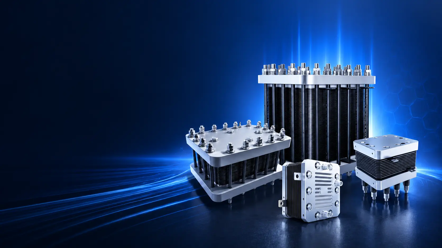
A detailed engineering and procurement guide for selecting PEM water-electrolysis stacks, controlling active area and cell count, pressure, water, thermal, mechanical and electrical interfaces, test evidence, durability and OEM responsibility.
1. Why PEM Electrolyzer Stacks Matter in Green Hydrogen Production
The stack is the electrochemical core of a PEM water-electrolysis system. It determines how the selected cell architecture converts DC current and water into hydrogen and oxygen, and it strongly influences voltage, heat generation, pressure arrangement, gas crossover behavior, footprint, service strategy and a large part of lifecycle cost. It does not, however, determine every result measured at the system outlet. Water treatment, rectification, cooling, separation, drying, purification and control logic remain part of the complete performance chain.
This distinction is central for OEMs and system integrators. A stack can meet its factory test while the assembled system misses output, purity or energy expectations because the rectifier, water loop, pressure control, thermal system or analyzer boundary differs from the test setup. The purchase specification must link the stack design to the intended balance of plant and state which party owns each interface.
What the stack directly influences
| Area | Stack influence | System factors that still matter |
|---|---|---|
| Hydrogen output | Cell count, active area, current and electrochemical efficiency establish the stack production basis. | Reference conditions, gas measurement, separator behavior and downtime affect delivered production. |
| Voltage and DC energy | Cell/stack voltage at defined current, temperature and pressure is a core stack characteristic. | Rectifier efficiency and pumps, cooling, drying and controls affect AC system energy. |
| Pressure capability | Seals, plates, manifolds, membrane support and compression define the stack pressure boundary. | Separators, piping, valves, dryers and downstream compression define system delivery pressure. |
| Gas crossover | Membrane, differential pressure, current/load and cell condition affect crossover. | Sampling point, purge, separation, monitoring and shutdown logic affect measured gas quality and safety. |
| Durability | Materials, build quality and electrochemical duty affect degradation. | Water, temperature, pressure control, cycling, maintenance and off-design operation affect field life. |
Start with the OEM design basis
Before asking for a quotation, prepare the target hydrogen flow or mass, reference conditions, electrical window, expected current profile, water specification, temperature, hydrogen and oxygen pressures, permitted differential pressure, cooling method, envelope, manifolds, terminals, sensors, control/protection strategy and required test points. For a replacement stack, provide drawings, photographs, nameplate, connection details and operating history—but do not assume that matching outer dimensions proves internal or electrochemical compatibility.
New design, replacement and scale-up are different purchases
- A new OEM design needs interface development, prototype validation and change control.
- A replacement needs verified mechanical, fluid, electrical and control compatibility with the existing system.
- A scale-up needs evidence that cell or short-stack behavior remains valid at production-stack size and operating conditions.
- Series production needs controlled sources, repeatability, inspection plans and notification of design/process changes.
Product identity: Specify a PEM water-electrolysis stack. PEM fuel-cell stacks use the reverse energy-conversion function and are not interchangeable even when some material names sound similar.
2. What Is a PEM Electrolyzer Stack?
A PEM electrolyzer stack contains multiple electrochemical cells connected electrically in series and arranged with common fluid manifolds and mechanical compression. Each repeating unit brings together the membrane/electrode region, porous transport or current-collection layers, flow-field or bipolar interfaces and seals. End plates, tie rods or other compression hardware maintain contact and sealing; terminals carry current; ports connect the water, hydrogen and oxygen circuits to the OEM balance of plant.
Define the supplied boundary
Suppliers use 'stack' and 'module' differently. One offer may include only the compressed cell assembly. Another may add sensors, insulation, local piping, pressure hardware, water fittings, gas separators or a support frame. The buyer should request an exploded scope list and interface-control drawing, then classify every item as included, optional, customer-supplied or outside scope.
| Boundary item | Questions to close | Controlled document |
|---|---|---|
| Mechanical envelope | Overall size, mass, center of gravity, supports, orientation, lifting and service removal. | General arrangement and installation drawing. |
| Fluid interfaces | Port type/location, flow direction, materials, pressure/temperature, purge, drain and vent. | Interface-control drawing and P&ID boundary. |
| Electrical interfaces | Polarity, terminal geometry, current, contact area, insulation, creepage/clearance and protection. | Electrical interface drawing and rectifier requirements. |
| Instrumentation | Voltage taps, temperature/pressure sensors, connector/pinout, accuracy and ownership. | Instrument list, I/O or connector schedule. |
| Compression/service | Factory-set load, permitted field adjustment, seal replacement and disassembly restrictions. | Assembly/service instruction and warranty conditions. |
| Test connections | Temporary or permanent test ports, sampling, isolation and safe depressurization. | Test schematic and FAT procedure. |
Active area and cell count
Active area should use the supplier's documented convention and remain consistent in calculations. Cell count affects stack voltage, while current and active area relate to current density and production. Do not estimate active area from the outside dimensions. Frames, manifolds, seals and compression hardware occupy space, and different designs use different electrochemically active boundaries.
What a stack datasheet should contain
- Model/build revision, cell count and active-area convention.
- Rated and permitted current, voltage, temperature and pressure conditions.
- Hydrogen/oxygen pressure arrangement and differential-pressure limits.
- Water quality, inlet temperature, flow and cooling requirements.
- Fluid/electrical/mechanical interfaces and permitted orientation.
- Performance-test basis, conditioning and gas reference conditions.
- Storage, transport, installation, startup, shutdown and service limitations.
Scope rule: A bare stack does not include the functions required to deliver dry, purified, compressed and safely controlled hydrogen unless those functions are explicitly included in the quoted module.
3. How PEM Electrolyzer Stacks Work
Water reaches the anode-side flow structure and porous transport layer. The oxygen-evolution catalyst supports the reaction that forms oxygen, protons and electrons. Protons pass through the hydrated membrane; electrons pass through the external electrical path. At the cathode, the hydrogen-evolution reaction forms hydrogen. Repeating cells are connected in series, so a production stack combines the behavior of many interfaces and must maintain reasonably uniform current, flow, temperature, pressure and compression.
| Step | Inside the stack | Engineering consequence |
|---|---|---|
| 1. Water distribution | Feed water is distributed through manifolds and channels to the reaction area. | Uneven flow, contamination or gas blockage can create nonuniform cell conditions. |
| 2. Oxygen evolution | Water is oxidized at the anode catalyst layer. | Anode materials and interfaces face an oxidizing, acidic and electrically loaded environment. |
| 3. Proton transport | Protons cross the hydrated membrane. | Membrane hydration, temperature, differential pressure and impurities affect resistance and crossover. |
| 4. Electron flow | Electrons travel through plates, contacts, terminals and the external DC circuit. | Contact resistance and current distribution affect voltage, heat and local stress. |
| 5. Hydrogen evolution | Hydrogen forms at the cathode and exits through the gas path. | Pressure, drainage, purge and gas removal must remain within the approved operating window. |
| 6. Heat and gas removal | Reaction heat and gases are removed by water and thermal/fluid systems. | The OEM cooling, separation and controls have to match the stack at every relevant load. |
Current, voltage and production
The relationship between current and hydrogen production is grounded in electrochemistry, but an order-specific output value still needs current, operating state, Faradaic efficiency, gas measurement and reference conditions. Stack voltage changes with current density, temperature, pressure, membrane and contact condition. A single rated point does not describe the permitted operating envelope or dynamic behavior.
Pressure and differential pressure
Hydrogen and oxygen sides may operate at similar or different pressures depending on architecture. The specification should state normal, minimum, maximum and transient pressures on both sides, as well as permitted differential pressure during startup, operation, shutdown and fault response. A pressure test confirms the integrity of the stated boundary under its procedure; it does not by itself prove gas crossover, electrochemical performance or long-term durability.
Low-load operation and crossover
At low production, the ratio between permeating gas and generated gas can change, so system monitoring and control limits need careful definition. The stack supplier and OEM should agree how gas analysis, purge, pressure control, minimum load and shutdown logic protect the operating envelope. Final gas purity after drying or purification is a different measurement from crossover at or near the stack.
Thermal and water coupling
Higher current increases production and heat. Water flow and temperature influence hydration, gas removal and heat transport. The OEM should not treat stack heat rejection as a fixed number independent of current and voltage. Request a heat-load or thermal basis over the intended range, plus alarm and trip limits for flow and temperature.
Data required to interpret a stack test
- Stack revision, cell count, active area and conditioning history.
- Water quality, flow and inlet temperature.
- Hydrogen/oxygen pressures and differential pressure.
- Current steps, current-density basis, voltage and stabilization method.
- Gas-flow measurement, reference conditions and analyzer/sampling details.
- Test duration, interruptions, beginning/end state and raw-data availability.
4. Main Components of a PEM Electrolyzer Stack
Stack performance comes from the interaction of electrochemical, fluid, electrical and mechanical parts. Procurement should avoid reducing quality to one premium material or one catalyst-loading statement. The buyer needs controlled specifications and measurable acceptance features at the appropriate level, while the supplier retains confidential design know-how.
| Component | Role | Failure or variation to consider | Purchasing control |
|---|---|---|---|
| Membrane / catalyst-coated membrane | Conducts protons and supports gas separation and electrochemical reactions. | Pinholes, contamination, poor handling, thickness variation, chemical or mechanical damage. | Approved specification/source, lot control, handling and change notification. |
| Catalyst layers | Support oxygen and hydrogen evolution reactions. | Loading/uniformity, adhesion, degradation and differences between qualification and production build. | Measurable process/specification controls and representative qualification evidence. |
| Porous transport/current-collection layers | Distribute fluids and current and support gas removal. | Porosity, thickness, coating/contact resistance, deformation, contamination and compression sensitivity. | Material/coating specification, dimensional/visual checks and source control. |
| Bipolar/flow-field plates | Carry current, distribute water/gases and form part of the cell boundary. | Material/coating defects, channel geometry, flatness, corrosion, contact resistance and pressure drop. | Drawing revision, material/coating evidence and controlled inspection. |
| Seals/gaskets | Separate hydrogen, oxygen, water and the environment. | Material incompatibility, aging, storage, surface damage, compression variation and groove mismatch. | Approved material, lot/expiry, clean handling, assembly and leak-test record. |
| Frames/manifold features | Locate components and distribute fluids among cells. | Dimensional mismatch, blockage, dead legs, cross-communication, drainage and chemical compatibility. | Dimensional inspection, cleanliness and interface drawing. |
| End plates | Distribute compression and provide structural support. | Deflection, corrosion, insulation, port/support loads and uneven pressure. | Material/drawing, load/deflection basis and final inspection. |
| Tie rods/fasteners/compression hardware | Maintain the specified assembly load. | Torque-load uncertainty, relaxation, alignment, galling and unauthorized adjustment. | Assembly procedure, calibrated tools, recorded torque/load and field restrictions. |
| Terminals/bus interfaces | Transfer high DC current to the stack. | Contact resistance, hot spots, oxidation, insufficient area, polarity and mechanical loading. | Interface drawing, surface/contact requirement and thermal/electrical checks. |
| Sensors and voltage taps | Provide protection, monitoring and diagnostics. | Incorrect location, loose connections, noise, calibration, connector errors and data interpretation. | Instrument/connector schedule, function test and calibration where applicable. |
Compression is a design parameter
Compression affects electrical contact, sealing and the deformation of porous and sealing components. It should be applied using the supplier's controlled method and maintained by the mechanical design. Field retightening without a procedure can shift load distribution, damage components or invalidate test and warranty conditions. The installation manual should state whether any check or adjustment is permitted.
Cleanliness and handling
Particles, oils, fibers, fingerprints, packaging debris or unsuitable cleaning residues can affect sealing, interfaces and water quality. Ask how critical components are stored and handled, how assembly cleanliness is controlled and how the finished stack is dried, preserved, sealed and packaged. Transport orientation, shock, freezing and storage temperature/humidity limitations should be stated.
Traceability at a useful level
Full disclosure of proprietary formulations is not necessary for traceability. The supplier can link the serial number or build record to controlled lots, assembly revision, in-process inspection, test result and deviations. The purchase order should define which records are delivered and which must be retained by the supplier for an agreed period.
Buyer focus: Ask for evidence that the production stack matches the qualified design and controlled process. A material certificate alone does not establish electrochemical performance, and a performance curve alone does not establish production traceability.
5. HELE Titanium PEM Electrolyzer Stack Series Comparison
The original HELE framework groups stacks by hydrogen-production direction, from low-flow laboratory units to larger OEM and project modules. These categories are useful for routing an inquiry, but published ranges should be treated as preliminary selection information. Current availability, precise model, test conditions, reference conditions, pressure, electrical window, interfaces and included components must be confirmed in the quotation.
| Original public category | Indicative production direction | Typical starting use | What must be confirmed |
|---|---|---|---|
| Small PEM Stack Series | 60–7000 ml/min | Laboratory supply, sensor/fuel-cell testing, education and component research. | Gas reference conditions, flow stability, pressure, electrical input, water/thermal control and safe integration. |
| Compact PEM Stack | 0.01–1 Nm³/h | Small OEM devices, portable or distributed hydrogen equipment and pilot work. | Current/voltage window, BoP interfaces, pressure differential, cooling and qualification scope. |
| Standard PEM Stack | 1–10 Nm³/h | OEM integration, pilot systems and small industrial hydrogen production. | Active area/cell count, duty cycle, rectifier, water/cooling, manifolds and test method. |
| Medium PEM Stack | 10–50 Nm³/h | Mid-scale on-site production and modular industrial systems. | Module architecture, common BoP, redundancy, service access, dynamic duty and acceptance evidence. |
| MW Large PEM Stack direction | 50–300 Nm³/h | Larger modular projects and industrial hydrogen plants. | Current model/build availability, module count, system scale-up, pressure/thermal design, factory/site test and lifecycle plan. |
Small-stack sub-series from the original framework
| Original low-flow range | Converted directional range | Typical evaluation focus |
|---|---|---|
| 60–300 ml/min | 0.0036–0.018 Nm³/h | Low-flow stability, analyzer/sensor use, safe venting and compact interfaces. |
| 600–1000 ml/min | 0.036–0.06 Nm³/h | Laboratory integration, data acquisition, water quality and repeatable test conditions. |
| 1200–2000 ml/min | 0.072–0.12 Nm³/h | Pilot testing, controlled pressure/flow, cooling and extended operation. |
| 3200–7000 ml/min | 0.192–0.42 Nm³/h | Larger laboratory or small distributed systems, BoP coordination and serviceability. |
The converted values above follow the original public framework and are not an order guarantee. A conversion between ml/min and Nm³/h depends on the stated reference conditions; the quotation should use one agreed basis throughout. Do not combine the maximum flow from one setup with the maximum pressure, purity or efficiency from another setup and describe them as one operating point.
How to use the range table
- Choose a provisional range from required hydrogen output and operating hours.
- Check whether one stack, parallel stacks or a modular architecture fits the availability and service plan.
- Match current/voltage to the rectifier and power-distribution design.
- Confirm hydrogen and oxygen pressures, differential pressure and gas-handling strategy.
- Freeze water quality/flow, cooling, manifolds, ports, terminals, sensors and mounting interfaces.
- Define prototype, qualification and production tests before selecting only on nominal flow.
Current availability must be confirmed
Because model ranges and production builds can change, HELE should confirm the offered model, manufacturing ownership, current drawings and test evidence before the page or quotation presents a configuration as available. If a historical model is replaced or customized, the new revision should be clearly identified rather than treated as identical.
Series-selection outcome: The output range narrows the search. The approved interface drawing, datasheet, test procedure and responsibility matrix select the stack.
6. How to Select the Right PEM Stack
Stack selection is an interface-matching exercise. Begin with what the OEM system must deliver, translate that requirement into an electrical, fluid, pressure, thermal and mechanical duty for the stack, and then verify that the proposed stack has been tested under relevant conditions. Selecting by hydrogen flow alone leaves the most difficult integration work unresolved.
| Selection factor | Information to provide | Supplier response required | Common mistake |
|---|---|---|---|
| Hydrogen duty | Normal/minimum/peak flow or mass, reference conditions, hours and cycle. | Proposed current, cell count/module arrangement, operating range and output method. | Treating a maximum catalogue flow as a continuous guaranteed point. |
| Electrical window | Available DC current/voltage or rectifier concept, ripple and dynamic profile. | Rated/permitted current and voltage, terminal interface, protection and heat behavior. | Matching only kW without checking current and voltage. |
| Water | Quality, temperature, flow, source treatment and monitoring. | Required limits, manifolding, pressure, low-flow protection and excursion response. | Using source-water conductivity as the complete water specification. |
| Pressure | H₂ and O₂ normal/max/transient pressure and permitted system differential. | Stack differential limits, test boundary, purge/drain and protection needs. | Quoting hydrogen pressure without oxygen-side or transient conditions. |
| Thermal | Inlet temperature, cooling medium, ambient and heat-removal capacity. | Heat-load basis, temperature limits, flow and sensor/alarm needs. | Sizing cooling only at one nominal point. |
| Mechanical | Envelope, orientation, supports, mass, access and replacement path. | GA, loads, lifting, service clearance and transport/storage limits. | Assuming dimensional fit means functional compatibility. |
| Fluid/electrical interfaces | Piping standards, ports, bus/cable and sensor/control architecture. | ICD, materials, ratings, polarity, pinout and mating responsibility. | Leaving adapters and transition pieces to site improvisation. |
| Duty and durability | Steady/dynamic operation, starts/stops, standby and expected life definition. | Qualification evidence, limits, degradation basis and warranty data requirements. | Comparing lifetime numbers without duty or end-of-life definition. |
Selection workflow
First freeze the OEM design basis and rank mandatory versus preferred requirements. Second, receive a preliminary stack proposal and interface data. Third, conduct a joint design review covering rectifier, water, gas, cooling, pressure, controls and mechanical integration. Fourth, agree prototype and qualification tests. Fifth, freeze the production revision, acceptance plan and change-control rules. The order should show which items remain open and what evidence will close them.
Replacement-stack review
For replacement projects, collect the operating history before selecting a new stack: water data, rectifier/current profile, temperatures, hydrogen and oxygen pressures, differential pressure events, alarms, starts/stops, gas analysis, failure symptoms and maintenance. A new stack may expose a BoP problem that contributed to the original failure. Confirm that the existing system can enforce the new stack's limits and that controls and safety functions are updated where necessary.
Prototype and production stages
Do not assume that a successful prototype automatically defines production acceptance. The prototype may use additional instrumentation, hand-selected components or a different test duration. Agree which design and process characteristics are frozen, which changes require notification, how first-article or qualification units are approved and what routine tests apply to every production stack.
Minimum RFQ data for stack selection
- Application and whether the request is new design, replacement, research or series production.
- Hydrogen duty and gas reference conditions.
- DC current/voltage/power window and operating profile.
- Water quality, flow, temperature and cooling conditions.
- Hydrogen/oxygen pressure and differential-pressure cases.
- Envelope, mounting, ports, terminals, sensors and service access.
- Required tests, documents, prototype quantity and annual demand.
7. PEM Stack vs Complete PEM Electrolyzer System
A stack purchase is appropriate when the buyer can design and validate the balance of plant around it. A complete system purchase is appropriate when the buyer wants the supplier to integrate defined power, water, gas, thermal, control and safety functions. Neither route is automatically better. The decision depends on internal engineering capability, schedule, intellectual-property strategy, certification route, service model and who is prepared to accept system-level performance responsibility.
| Decision area | PEM stack supply | Complete electrolyzer system | Question for the buyer |
|---|---|---|---|
| Core scope | Compressed electrochemical assembly with defined interfaces. | Stack plus order-defined BoP, controls and package integration. | Which subsystems can the OEM design, source and validate? |
| Electrical | Buyer integrates rectifier, protection and distribution. | Rectifier/control may be included to the stated AC or DC boundary. | Who guarantees electrical compatibility and energy measurement? |
| Water/thermal | Buyer designs treatment, circulation and cooling. | Defined water and cooling equipment may be included. | Who protects the stack from water or thermal excursions? |
| Gas delivery | Buyer handles separation, conditioning, analysis and downstream equipment. | Separators and optional drying/purification may be included. | Where are pressure, purity and dew point guaranteed? |
| Controls/safety | Buyer develops sequence, monitoring and system protection. | PLC/HMI and package safety functions may be integrated. | Who owns cause-and-effect and site integration? |
| Testing | Stack-level tests under a defined test stand. | System FAT under an order-defined package boundary. | Which tests prove stack acceptance versus system acceptance? |
| Lifecycle service | OEM manages BoP diagnosis and stack operating evidence. | Supplier may support an integrated package within agreed scope. | Who performs first-line troubleshooting and holds spares? |
When stack supply makes sense
OEMs with established rectifier, water, thermal, gas and control platforms may prefer stack supply to retain system architecture and service ownership. They still need a formal interface-control process and should involve the stack supplier before freezing operating limits or protection logic. A stack supplier cannot validate a system it has not reviewed, and an OEM cannot assume a catalogue stack will tolerate an undisclosed duty.
When a complete package makes sense
End users, demonstration projects and teams without electrolysis integration capability may reduce interface risk by purchasing a more complete package. The phrase complete must be converted into an equipment list and battery-limit drawing. Compression, storage, building ventilation, site piping, foundations, permits and EPC work often remain outside even when the package is described as complete.
Hybrid supply
Many projects sit between the two options. The supplier may provide a stack and selected process module while the OEM supplies rectification, enclosure and controls. Hybrid supply can be effective when the design authority and acceptance tests are explicit. Use a responsibility matrix for design, procurement, software, safety analysis, testing, installation and warranty data.
Boundary rule: Do not assign delivered purity, dew point, AC energy consumption, compressor performance or site compliance to a bare stack. Those outcomes depend on equipment and responsibilities beyond the stack boundary.
Make-or-buy decision
- Internal capability exists for water, gas, thermal, electrical, controls and hydrogen safety engineering.
- The party carrying system-performance responsibility is named.
- Certification and site-permitting responsibilities are understood.
- Prototype and system-validation facilities are available.
- Field service, data retention, spares and warranty diagnosis are assigned.
- Commercial comparison includes all omitted BoP and integration work.
8. PEM Stack Quality Evaluation and Purchase Guard
A quality review should answer three questions: Is the offered stack the same controlled design that was qualified? Was the ordered unit assembled and tested using the agreed process? Can the buyer demonstrate that the stack was operated within its limits if performance changes later? Those questions require a combination of design control, production evidence, test methods and operational data—not a single certificate.
Supplier and design review
Confirm design authority, manufacturing ownership and the role of critical component suppliers. Ask how materials, drawings, processes and software/test procedures are revised and approved. For series supply, define notification requirements for changes to MEA-related components, PTLs, plates/coatings, seals, compression hardware, manifolds or test methods. The goal is not to prevent improvement; it is to avoid an unreviewed change to a qualified interface or performance basis.
Inspection and test plan
| Stage | Suggested control | Record or decision |
|---|---|---|
| Incoming/critical components | Identity, condition, dimensions or defined supplier evidence. | Accepted lot/source or nonconformance disposition. |
| Assembly | Clean handling, orientation, alignment, seal placement, compression and calibrated tools. | Build traveler linked to serial/build revision. |
| Dimensional/electrical inspection | Envelope, ports, supports, terminals, insulation and sensor connections. | Inspection report against approved ICD/GA. |
| Pressure/leak | Defined medium, separate/common boundaries, pressure, differential, duration and acceptance. | Signed test record with instruments and configuration. |
| Conditioning/performance | Water, temperature, pressure, current steps, stabilization and hydrogen measurement. | Raw/processed data and acceptance result. |
| Gas/crossover | Sampling point, analyzer/calibration, load and pressure conditions. | Result tied to the tested configuration and method. |
| Release | Documentation, deviations, cleanliness, preservation, packing and labels. | Release note and data dossier. |
Durability and end-of-life
Define whether durability evidence is a material/cell test, short-stack qualification, production-stack test, accelerated stress test or field record. State operating point, dynamic cycle, water, temperature, pressure, starts/stops, duration and interruptions. End of life may be defined through voltage increase, efficiency loss, gas crossover, inability to meet output or another agreed criterion. Accelerated testing needs a stated relationship to the intended duty; it should not be converted directly into a guaranteed number of field hours without evidence.
Factory acceptance
The FAT procedure should name the exact stack revision and test stand, utilities, instruments, calibration, conditioning, operating points, stabilization, data rate, calculations and acceptance. Separate pressure/leak, electrical/insulation, functional, performance and gas/crossover tests. Agree what happens when a result is outside tolerance, what can be corrected, which tests are repeated and how deviations are recorded.
Evidence after delivery
Warranty investigation depends on operating evidence. The OEM should retain current and voltage, water quality/flow, temperatures, hydrogen/oxygen pressures, differential pressure, gas analysis, alarms, starts/stops, rectifier events and maintenance. Before disassembly, check sensors and BoP functions and preserve the stack in a controlled state. Unplanned opening can destroy evidence and create additional damage.
Final PEM Stack Purchase Guard
Do not release the purchase order until these items align
- The product is a PEM water-electrolysis stack with a controlled model/build revision.
- Hydrogen/electrical duty and gas reference conditions are defined.
- Active area, cell count, current, voltage and pressure arrangements are stated.
- Water, thermal, differential-pressure and dynamic operating limits are agreed.
- Mechanical, fluid, electrical, sensor and service interfaces are frozen in an ICD/GA.
- Prototype, qualification, routine acceptance and production change-control requirements are separated.
- Pressure/leak, performance and gas/crossover methods identify configuration, instruments and acceptance.
- Durability, end-of-life, warranty and required operating evidence use the same duty basis.
- Documents, spares, packing, Incoterm, schedule, annual volume and exclusions are recorded.
Decision gate: A technically acceptable stack is one the OEM can integrate and protect, and whose ordered performance can be inspected under agreed conditions. A strong brochure or isolated peak result is not a substitute for that controlled chain.
Technical references
- U.S. DOE — Technical targets for proton exchange membrane electrolysis
- ISO 22734-1:2025 — Hydrogen generators using water electrolysis — Part 1: Safety
- NLR / DOE — In situ testing capabilities for hydrogen generation
DOE targets are development guideposts and distinguish stack and system characteristics. The NLR/DOE testing page illustrates why operating conditions, diagnostic methods and equipment bounds matter. ISO 22734-1:2025 addresses safety requirements for hydrogen generators; applicability or certification of a specific stack/system configuration must be confirmed separately.