Before you request a quote
A reliable order begins with the service conditions and the finished function of sacrificial anodes—not with the product name alone. For applications involving galvanic cathodic protection of marine, buried, immersed and internal structures, magnesium, zinc and aluminum alloys have different potentials, capacities and environments; net alloy mass, insert, utilization, installation and design current determine protection.
Before comparing suppliers, define the operating conditions, required configuration, interfaces, supply boundary and acceptance evidence. Require each quotation to identify the proposed basis, assumptions, exclusions and deliverable records so that technical differences remain visible.
A reliable sacrificial-anode order is not a request for “some zinc” or a target weight. It is a controlled cathodic-protection basis linking the environment, protected structure, current demand, capacity, current output, alloy, geometry, installation and acceptance evidence.
1. Define the Asset and Supply Boundary
Name the structure, protected material, location, new-build or retrofit status, operating profile, design code, owner specification and design authority. State whether the supplier provides anodes only, anode assemblies, calculations, layout support, installation items, testing, supervision or commissioning.
- Identify marine hull, ballast tank, offshore structure, subsea pipeline, buried pipeline, tank, water system or another asset.
- List included inserts, brackets, straps, cables, backfill, junctions, monitoring items, spares and documents.
- Assign responsibility for coating breakdown, CP calculations, interference review, structural welding and field performance.
- Control drawing, specification and calculation revisions and their order of precedence.
Procurement recommendation
Define the Asset and Supply Boundary is not an isolated specification line. For sacrificial anodes used in galvanic cathodic protection of marine, buried, immersed and internal structures, magnesium, zinc and aluminum alloys have different potentials, capacities and environments; net alloy mass, insert, utilization, installation and design current determine protection. Connect this requirement to the actual service conditions, interfaces and acceptance evidence before releasing the order.
Select magnesium, zinc or aluminum alloy from environment, resistivity/salinity, temperature, structure potential and CP design. Record the selected basis, supplier assumptions and any unresolved interface in the quotation and approved order documents.
- structure, electrolyte/soil/seawater and coating condition
- anode alloy and governing composition specification
- design current, capacity, utilization and design life
- gross/net mass and dimensions
- alloy chemistry certificate
- weight and dimensional inspection
2. Confirm the Galvanic Protection Principle
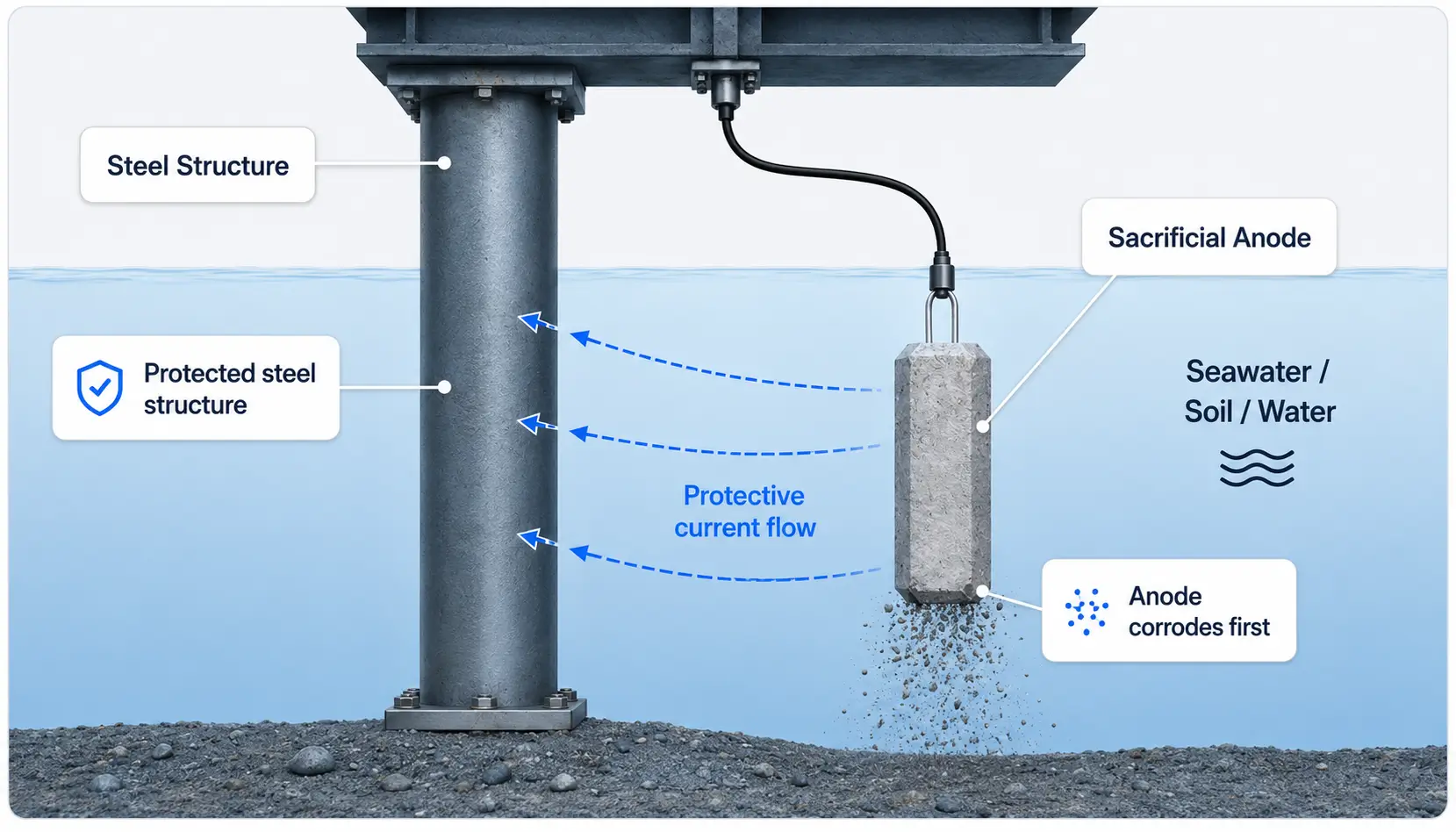
A galvanic anode provides sacrificial protection when it is electrically coupled to a more noble structure in a shared electrolyte. The electrochemical potential difference drives protective current and consumes the anode. This requires more than physical proximity.
Electrical continuity, electrolyte path, suitable driving voltage, adequate current output, correct distribution and sufficient usable capacity.
Structure-wide potential distribution, coating condition, isolation, installation quality, interference control or full design-life performance.
Procurement recommendation
Confirm the Galvanic Protection Principle is not an isolated specification line. For sacrificial anodes used in galvanic cathodic protection of marine, buried, immersed and internal structures, magnesium, zinc and aluminum alloys have different potentials, capacities and environments; net alloy mass, insert, utilization, installation and design current determine protection. Connect this requirement to the actual service conditions, interfaces and acceptance evidence before releasing the order.
Select magnesium, zinc or aluminum alloy from environment, resistivity/salinity, temperature, structure potential and CP design. Record the selected basis, supplier assumptions and any unresolved interface in the quotation and approved order documents.
- anode alloy and governing composition specification
- design current, capacity, utilization and design life
- gross/net mass and dimensions
- steel insert/core, attachment and contact
- weight and dimensional inspection
- insert/core inspection
3. Characterize the Environment, Structure and Coating
Record the electrolyte or soil and its variability: salinity or composition, resistivity/conductivity, temperature, pH where relevant, oxygenation, flow, depth, burial, moisture, sediment, seasonal range and contaminants. Define structure area, material, joints, continuity, isolation and nearby metallic systems.
- Describe coating/lining type, age, condition, breakdown factor and exposed area basis.
- Separate immersed, tidal, splash, mud-zone, soil and internal-water conditions where applicable.
- Identify electrical isolation joints, bonds, test stations and monitoring locations.
- Record inspection access, anode replacement constraints and hazards.
Required service data
Sacrificial anodes may be used in galvanic cathodic protection of marine, buried, immersed and internal structures. The application name is only a starting point. The purchasing basis should state the actual medium, temperature, load or current, duty cycle, geometry, installation and consequence of failure. Those details determine whether the proposed grade, construction and test plan are relevant.
The recurring risk is that magnesium, zinc and aluminum alloys have different potentials, capacities and environments; net alloy mass, insert, utilization, installation and design current determine protection. Record unknown information as an open item; do not replace it with a supplier default and later treat that default as a customer requirement.
Questions to close
- design current, capacity, utilization and design life
- gross/net mass and dimensions
- steel insert/core, attachment and contact
- potential/capacity test, marking and traceability
- structure, electrolyte/soil/seawater and coating condition
4. Select Aluminum, Zinc or Magnesium from the Project Environment
Material families cannot be selected from application name alone. Aluminum is commonly evaluated for selected seawater/offshore duties; zinc for seawater, brackish and selected saline environments; magnesium for selected soil, freshwater and higher-resistance environments. Exact alloy, chemistry, potential and capacity basis remain project-specific.
| Family | Starting review | Do not omit |
|---|---|---|
| Aluminum | Selected marine/offshore environments | Alloy chemistry, activation/passivation boundary, temperature/salinity, potential, capacity, class/owner basis |
| Zinc | Seawater, brackish and selected saline service | Applicable material specification, impurities, environment, potential/capacity, geometry and qualification |
| Magnesium | Selected soil, freshwater and higher-resistance service | Alloy type, soil/resistivity, backfill, potential, output, interference and installation |
Use the dedicated aluminum, zinc and magnesium pages after the family is selected.
Required service data
Sacrificial anodes may be used in galvanic cathodic protection of marine, buried, immersed and internal structures. The application name is only a starting point. The purchasing basis should state the actual medium, temperature, load or current, duty cycle, geometry, installation and consequence of failure. Those details determine whether the proposed grade, construction and test plan are relevant.
The recurring risk is that magnesium, zinc and aluminum alloys have different potentials, capacities and environments; net alloy mass, insert, utilization, installation and design current determine protection. Record unknown information as an open item; do not replace it with a supplier default and later treat that default as a customer requirement.
Questions to close
- gross/net mass and dimensions
- steel insert/core, attachment and contact
- potential/capacity test, marking and traceability
- structure, electrolyte/soil/seawater and coating condition
- anode alloy and governing composition specification
5. Freeze Protection Criteria and Reference-Electrode Scale
State the governing standard or owner specification, protection criterion, potential range, reference electrode and conversion basis where needed. Do not quote a potential without identifying the reference scale, measurement location and operating condition.
- Define native/baseline, polarization, instant-off or other measurement basis where applicable.
- State overprotection limits or coating/material constraints where required.
- Define measurement locations, instrument input resistance, calibration and correction needs.
- Separate design targets from commissioning and long-term acceptance criteria.
Procurement recommendation
Freeze Protection Criteria and Reference-Electrode Scale is not an isolated specification line. For sacrificial anodes used in galvanic cathodic protection of marine, buried, immersed and internal structures, magnesium, zinc and aluminum alloys have different potentials, capacities and environments; net alloy mass, insert, utilization, installation and design current determine protection. Connect this requirement to the actual service conditions, interfaces and acceptance evidence before releasing the order.
Select magnesium, zinc or aluminum alloy from environment, resistivity/salinity, temperature, structure potential and CP design. Record the selected basis, supplier assumptions and any unresolved interface in the quotation and approved order documents.
- steel insert/core, attachment and contact
- potential/capacity test, marking and traceability
- structure, electrolyte/soil/seawater and coating condition
- anode alloy and governing composition specification
- marking/heat-lot traceability
- alloy chemistry certificate
6. Establish Initial, Maintenance and Final Design Current
Current demand depends on protected area, environment, current-density basis, coating breakdown or bare-surface fraction, polarization state and life stage. The calculation should show inputs, units, factors, safety margins and the governing case.
Calculation relationship
Design current is generally built from the relevant protected area and the specified current-demand basis, adjusted for coating condition, life stage and project factors. Use the governing design standard and owner criteria; do not import an unconditioned current-density number.
- Separate initial polarization, maintenance and final-life current where the design method requires them.
- Show coating breakdown development and exposed-area assumptions.
- Address shielding, mud, compartments, isolated zones and non-uniform distribution.
- State whether adjacent structures, bonds or interference affect the demand.
Installation and operating controls
Install with verified metallic continuity and orientation; inspect consumption and structure potentials against the CP design. Installation and operating instructions should state permitted loads, chemistry or environment, handling, cleaning, inspection intervals and the data required for warranty review.
If performance changes, preserve the original condition and operating record before repair or adjustment. Wrong alloy/environment, low net mass, contaminated alloy, poor insert bond/contact and unsupported design-life claims cause underprotection. Photographs, measurements, alarms, water/electrolyte data, electrical data and maintenance history can distinguish a product defect from an interface or operating problem.
- potential/capacity test, marking and traceability
- structure, electrolyte/soil/seawater and coating condition
- anode alloy and governing composition specification
- design current, capacity, utilization and design life
- alloy chemistry certificate
- weight and dimensional inspection
7. Size Usable Capacity and Net Alloy Mass
Capacity sizing relates required current over the design period to the usable electrochemical capacity of the specified alloy. A common engineering relationship divides required ampere-hours by alloy capacity multiplied by utilization, with project factors applied as required by the governing method.
- State design current or time-varying current basis and design duration.
- State alloy capacity value, units, source/test basis and environmental correction.
- State utilization factor for the anode geometry and installation.
- State contingency, redundancy or safety factor and rounding method.
- Use net sacrificial alloy mass—not gross assembly weight—in the capacity calculation.
Required mass demonstrates capacity only under the stated assumptions. It does not prove that anodes can deliver the required current at the beginning or end of life.
Material or coating specification
Select magnesium, zinc or aluminum alloy from environment, resistivity/salinity, temperature, structure potential and CP design. The material or coating designation should appear beside the governing product specification, condition and service assumptions. A familiar grade name used under the wrong product standard can still produce the wrong supply.
Ask the supplier to identify the offered basis, permitted substitutions and the evidence used to confirm it. For proprietary or process-sensitive items, measurable acceptance and controlled change notification are more useful than demanding confidential formulation details.
- structure, electrolyte/soil/seawater and coating condition
- anode alloy and governing composition specification
- design current, capacity, utilization and design life
- gross/net mass and dimensions
- weight and dimensional inspection
- insert/core inspection
8. Check Current Output, Resistance and Distribution
Verify that each anode and the complete arrangement can deliver the required current under the design environment. The check normally considers driving voltage, anode resistance, electrolyte resistivity, anode geometry, burial/backfill or stand-off condition, spacing and polarization.
- State the anode-resistance formula or model and its applicability.
- Use dimensions representing the installed anode and relevant consumption state.
- Check initial and later-life output where the design method requires it.
- Review current distribution, shielding, mutual interference and structure access.
- Reconcile the number of anodes required by capacity, output and layout; the governing requirement controls.
Procurement recommendation
Check Current Output, Resistance and Distribution is not an isolated specification line. For sacrificial anodes used in galvanic cathodic protection of marine, buried, immersed and internal structures, magnesium, zinc and aluminum alloys have different potentials, capacities and environments; net alloy mass, insert, utilization, installation and design current determine protection. Connect this requirement to the actual service conditions, interfaces and acceptance evidence before releasing the order.
Select magnesium, zinc or aluminum alloy from environment, resistivity/salinity, temperature, structure potential and CP design. Record the selected basis, supplier assumptions and any unresolved interface in the quotation and approved order documents.
- anode alloy and governing composition specification
- design current, capacity, utilization and design life
- gross/net mass and dimensions
- steel insert/core, attachment and contact
- insert/core inspection
- closed-circuit potential/capacity evidence when ordered
9. Freeze Anode Geometry, Insert and Mounting
The drawing should define net alloy envelope, tolerances, insert/core, brackets, straps, cables, contact surfaces, welds, bolt holes, stand-off, clearances, lifting and orientation. Net alloy mass and gross assembly weight must be stated separately.
Weld-on or bolt-on interface, bracket material, stand-off, coating exclusion, access and hydrodynamic constraints.
Pipe OD, half-shell dimensions, gap, insert, coating interface, welding/clamping and field assembly.
Anode body, cable, connection/seal, backfill package, lead length, burial depth and installation.
Cross-section, length, core position, exposed insert, threads, contact, support and replaceability.
Drawing and interface controls
Define shape, net alloy mass, gross mass, insert geometry, weld-on/bolt-on attachment, stand-off and installation drawing. Use one measurement convention, identify datums or reference edges, and state whether dimensions apply before or after coating, forming, heat treatment, machining or other finishing.
Where fit-up or function depends on mating equipment, include the interface drawing rather than a standalone part sketch. The supplier should return a drawing for approval and record any proposed tolerance or feature change before production.
- design current, capacity, utilization and design life
- gross/net mass and dimensions
- steel insert/core, attachment and contact
- potential/capacity test, marking and traceability
- structure, electrolyte/soil/seawater and coating condition
10. Control Alloy, Insert and Manufacturing Route
Freeze the qualified source and route for alloy charge, insert preparation, casting or forming, trimming/machining, identification and packing. Process details vary by alloy and geometry; public descriptions do not replace the supplier's controlled instructions.
- Define raw-material identity, charge/batch traceability and chemistry sampling.
- Control insert material, cleanliness, preparation, position, exposure and bonding route.
- Define casting/fabrication visual criteria, critical dimensions and repair restrictions.
- Require approval and requalification for changes affecting alloy, insert, tooling, source or route.
Material or coating specification
Select magnesium, zinc or aluminum alloy from environment, resistivity/salinity, temperature, structure potential and CP design. The material or coating designation should appear beside the governing product specification, condition and service assumptions. A familiar grade name used under the wrong product standard can still produce the wrong supply.
Ask the supplier to identify the offered basis, permitted substitutions and the evidence used to confirm it. For proprietary or process-sensitive items, measurable acceptance and controlled change notification are more useful than demanding confidential formulation details.
- gross/net mass and dimensions
- steel insert/core, attachment and contact
- potential/capacity test, marking and traceability
- structure, electrolyte/soil/seawater and coating condition
- marking/heat-lot traceability
- alloy chemistry certificate
11. Match Inspection Evidence to the Requirement
| Requirement | Possible evidence when ordered | Boundary |
|---|---|---|
| Alloy chemistry | Heat/batch chemical analysis | Sampling and specification must be stated |
| Potential / capacity | Qualification, batch or certificate evidence under an agreed method | Reference electrode, electrolyte, temperature, conditioning and method matter |
| Net / gross mass | Calibrated weight record and sampling | Do not substitute gross weight for alloy mass |
| Dimensions / insert | Drawing-based dimensional and visual report | Hidden insert features may require process records or qualification samples |
| Traceability | Cast/lot/heat identification and document linkage | Extent follows the PO and ITP |
| Class / third party | Approved inspection plan, witness/hold points and certificates | Must be agreed before manufacture |
Inspection and acceptance evidence
Inspection is useful only when the characteristic, method, sampling, instrument, acceptance criterion and responsible party are known. For sacrificial anodes, a certificate can confirm the items within its scope; it does not prove unrelated dimensions, field performance or service life.
Agree the inspection and test plan before production. Identify review, witness and hold points, the treatment of nonconformances and whether raw readings, summarized reports or third-party records are required with shipment.
Records to request
- alloy chemistry certificate
- weight and dimensional inspection
- insert/core inspection
- steel insert/core, attachment and contact
- potential/capacity test, marking and traceability
- structure, electrolyte/soil/seawater and coating condition
12. Define Installation and Commissioning
Protect contact surfaces, cables and anode bodies during transport and installation. Confirm orientation, location, spacing, structural attachment, coating repair boundary, electrical continuity, isolation and test access before commissioning.
- Use qualified structural/welding procedures where the asset requires them.
- Prevent unintended coating damage and dissimilar-metal or short-circuit paths.
- Verify cable/connection sealing and backfill placement for buried designs.
- Record installed identity/location, continuity and baseline structure potentials.
- Define polarization/commissioning period, acceptance and corrective actions.
Procurement recommendation
Define Installation and Commissioning is not an isolated specification line. For sacrificial anodes used in galvanic cathodic protection of marine, buried, immersed and internal structures, magnesium, zinc and aluminum alloys have different potentials, capacities and environments; net alloy mass, insert, utilization, installation and design current determine protection. Connect this requirement to the actual service conditions, interfaces and acceptance evidence before releasing the order.
Select magnesium, zinc or aluminum alloy from environment, resistivity/salinity, temperature, structure potential and CP design. Record the selected basis, supplier assumptions and any unresolved interface in the quotation and approved order documents.
- potential/capacity test, marking and traceability
- structure, electrolyte/soil/seawater and coating condition
- anode alloy and governing composition specification
- design current, capacity, utilization and design life
- weight and dimensional inspection
- insert/core inspection
13. Plan Monitoring, Consumption Assessment and Replacement
Monitoring should compare measured structure potentials and anode condition with the approved design basis. Inspection frequency depends on asset criticality, environment, access, coating, design life and previous trends.
- Record reference-electrode type, calibration, location, operating condition and reading basis.
- Trend anode consumption, physical damage, detachment, cable/connection condition and shielding.
- Check coating deterioration, continuity, isolation and environmental changes.
- Define replacement criteria from remaining mass/geometry, output, potential distribution and remaining service period.
- Keep replacement anodes linked to the current—not merely original—design basis.
Procurement recommendation
Plan Monitoring, Consumption Assessment and Replacement is not an isolated specification line. For sacrificial anodes used in galvanic cathodic protection of marine, buried, immersed and internal structures, magnesium, zinc and aluminum alloys have different potentials, capacities and environments; net alloy mass, insert, utilization, installation and design current determine protection. Connect this requirement to the actual service conditions, interfaces and acceptance evidence before releasing the order.
Select magnesium, zinc or aluminum alloy from environment, resistivity/salinity, temperature, structure potential and CP design. Record the selected basis, supplier assumptions and any unresolved interface in the quotation and approved order documents.
- structure, electrolyte/soil/seawater and coating condition
- anode alloy and governing composition specification
- design current, capacity, utilization and design life
- gross/net mass and dimensions
- insert/core inspection
- closed-circuit potential/capacity evidence when ordered
14. Investigate Underprotection, Overprotection and Abnormal Consumption
Preserve potential surveys, reference-electrode checks, continuity/isolation measurements, environmental data, coating condition, anode location and consumption evidence before changing the system.
Review continuity, isolation, coating breakdown, current demand, anode passivation/detachment, resistance, shielding and placement.
Review actual current demand, coating loss, shorts/bonds, environment, alloy conformity, current distribution and stray-current interaction.
Review electrical connection, passivation, high resistance, backfill/installation, electrolyte access and measurement validity.
Check reference scale/calibration, location, IR effects, operating state, isolation and the applicable acceptance criterion.
Procurement recommendation
Investigate Underprotection, Overprotection and Abnormal Consumption is not an isolated specification line. For sacrificial anodes used in galvanic cathodic protection of marine, buried, immersed and internal structures, magnesium, zinc and aluminum alloys have different potentials, capacities and environments; net alloy mass, insert, utilization, installation and design current determine protection. Connect this requirement to the actual service conditions, interfaces and acceptance evidence before releasing the order.
Select magnesium, zinc or aluminum alloy from environment, resistivity/salinity, temperature, structure potential and CP design. Record the selected basis, supplier assumptions and any unresolved interface in the quotation and approved order documents.
- anode alloy and governing composition specification
- design current, capacity, utilization and design life
- gross/net mass and dimensions
- steel insert/core, attachment and contact
- closed-circuit potential/capacity evidence when ordered
- marking/heat-lot traceability
15. Decide Whether Galvanic or ICCP Is the Better System
Compare required current, structure size and geometry, environment, power availability, control range, monitoring, installation, replacement access, interference, redundancy, life-cycle cost and owner experience. Galvanic anodes are self-powered and consumed; ICCP uses external DC power and a different anode/control architecture.
A hybrid or retrofit decision requires a system-level study. Review HELE's impressed-current cathodic protection page when the project calls for powered and adjustable current.
Procurement recommendation
Decide Whether Galvanic or ICCP Is the Better System is not an isolated specification line. For sacrificial anodes used in galvanic cathodic protection of marine, buried, immersed and internal structures, magnesium, zinc and aluminum alloys have different potentials, capacities and environments; net alloy mass, insert, utilization, installation and design current determine protection. Connect this requirement to the actual service conditions, interfaces and acceptance evidence before releasing the order.
Select magnesium, zinc or aluminum alloy from environment, resistivity/salinity, temperature, structure potential and CP design. Record the selected basis, supplier assumptions and any unresolved interface in the quotation and approved order documents.
- design current, capacity, utilization and design life
- gross/net mass and dimensions
- steel insert/core, attachment and contact
- potential/capacity test, marking and traceability
- marking/heat-lot traceability
- alloy chemistry certificate
16. Normalize Technical and Commercial Quotations
Compare quotations only after material, net mass, electrochemical basis, geometry, insert, mounting and evidence have been aligned. A lower unit price may reflect less alloy, a different capacity/utilization basis, fewer documents or a different insert and installation scope.
- Compare net alloy mass and gross weight separately.
- Normalize alloy/specification, potential/capacity basis, utilization and design assumptions.
- Freeze drawing revision, tolerances, insert, attachment and quantity by model/location.
- Separate calculations, anodes, installation accessories, spares, inspection/class and freight.
- Record Incoterm, destination, packing, required date, validity, exceptions and change control.
Quotation comparison
For sacrificial anodes, a low unit price can conceal a different material basis, unfinished processing, reduced inspection, missing accessories or a narrower delivery responsibility. Compare offers only after each supplier has answered the same technical schedule and returned a marked list of assumptions, options and exclusions.
Alloy, net mass, casting size, insert, quantity, testing, freight and design documentation drive cost. The commercial comparison should also include document review, samples or destructive tests, packing, Incoterm, tooling or setup, first-article approval, spares and the treatment of deviations or rework.
Before order release
- gross/net mass and dimensions
- steel insert/core, attachment and contact
- potential/capacity test, marking and traceability
- structure, electrolyte/soil/seawater and coating condition
- anode alloy and governing composition specification
- alloy chemistry certificate
- weight and dimensional inspection
- insert/core inspection
Selection recommendation: Select magnesium, zinc or aluminum alloy from environment, resistivity/salinity, temperature, structure potential and CP design.
17. Complete Sacrificial Anode Purchase Guard
17.1 Asset, environment and responsibility
- Identify asset, materials, geometry, service, environment and governing documents.
- Define electrolyte/soil ranges, resistivity or salinity, temperature, flow/depth and variability.
- Assign CP design, calculations, layout, structural attachment, installation and performance responsibilities.
17.2 Structure, coating and criteria
- State protected/wetted area and segmentation.
- Define coating/lining type, condition, breakdown and exposed-area basis.
- State protection criteria, reference electrode/scale, measurement and overprotection boundary.
17.3 Current, capacity and output
- Show initial/maintenance/final current demand and governing case.
- State design life, alloy capacity, utilization, factors and required net mass.
- Show driving voltage, resistance/output method, dimensions, spacing and layout check.
17.4 Alloy and electrochemical basis
- State aluminum, zinc or magnesium alloy designation and chemistry limits.
- Define potential with reference scale, capacity and qualification/test method where required.
- Confirm environmental applicability and passivation/activation constraints.
17.5 Drawing, insert and mass
- Control model, drawing revision, dimensions, tolerances and orientation.
- Define insert/core material, preparation, position, exposure, connection and load requirement.
- State net alloy mass and gross assembly weight separately with tolerances.
17.6 Inspection and documentation
- Define chemistry, weight, dimensional, visual and electrochemical evidence.
- Set lot/heat/cast traceability, sampling and acceptance.
- Agree ITP, class/third-party witness, certificates, drawings and data book before manufacture.
17.7 Installation, monitoring and replacement
- Define mounting/welding/bolting/cable/backfill and coating-repair boundary.
- Confirm continuity, isolation, baseline readings and commissioning acceptance.
- Set monitoring frequency, consumption assessment, remaining-life and replacement criteria.
17.8 Commercial and change control
- Normalize anodes, accessories, spares, tests, documents and freight.
- State quantity by model/location, packing, Incoterm, destination, date and validity.
- Require approval for alloy, insert, source, tooling, route or drawing changes.
Red flags before purchase order
Environment, coating, design criteria and output have not been established.
Capacity, current output, resistance and distribution checks are missing.
The value cannot be compared or accepted reliably.
Insert/core mass may overstate usable sacrificial capacity.
Decision gate
Do not release the order until environment, structure/coating, protection criteria, current, capacity, output, alloy, net mass, drawing, insert, mounting, evidence and responsibilities describe one verifiable deliverable.
Quotation comparison
For sacrificial anodes, a low unit price can conceal a different material basis, unfinished processing, reduced inspection, missing accessories or a narrower delivery responsibility. Compare offers only after each supplier has answered the same technical schedule and returned a marked list of assumptions, options and exclusions.
Alloy, net mass, casting size, insert, quantity, testing, freight and design documentation drive cost. The commercial comparison should also include document review, samples or destructive tests, packing, Incoterm, tooling or setup, first-article approval, spares and the treatment of deviations or rework.
Before order release
- steel insert/core, attachment and contact
- potential/capacity test, marking and traceability
- structure, electrolyte/soil/seawater and coating condition
- anode alloy and governing composition specification
- design current, capacity, utilization and design life
- weight and dimensional inspection
- insert/core inspection
- closed-circuit potential/capacity evidence when ordered
Selection recommendation: Select magnesium, zinc or aluminum alloy from environment, resistivity/salinity, temperature, structure potential and CP design.
18. Sacrificial Anode Purchasing FAQ and References
What information should be fixed before alloy selection?
Define the asset, electrolyte or soil environment, resistivity or salinity, temperature, coating condition and breakdown basis, exposed area, protection criteria, design current, design life, geometry, installation and governing code or owner specification.
What is the difference between net and gross anode weight?
Net weight is the sacrificial alloy mass used in capacity calculations. Gross weight may include the steel insert, core or mounting hardware. Quotations should state both without substituting one for the other.
How is required anode mass determined?
A project calculation normally relates design current and design time to usable electrochemical capacity, including the specified alloy capacity and utilization factor. The code, safety factors, environmental corrections and owner criteria must be stated.
Why is a current-output check still needed after mass sizing?
Enough alloy mass does not prove that the installed anodes can deliver the required current. Output depends on driving voltage, anode resistance, geometry, electrolyte resistivity, spacing, installation and polarization conditions.
What evidence can accompany a sacrificial anode lot?
Depending on the order, evidence may include chemical composition, net/gross weight, dimensions, insert or core details, visual and dimensional inspection, casting identification, electrochemical qualification or certificates, drawings and traceability records.
When should ICCP be evaluated instead?
ICCP may merit evaluation when current demand, geometry, controllability, monitoring, available power, anode replacement access or life-cycle requirements make a galvanic system unsuitable. The choice belongs to the project CP design, not a generic product claim.
RFQ checklist
Asset, environment, coating, area, criteria, current, life and governing documents.
Alloy/specification, chemistry, capacity, potential, utilization, net and gross weight.
Model/drawing, dimensions, insert/core, bracket/cable/backfill, mounting and quantity.
Inspection, class/documents, packing, destination, Incoterm, required date and exceptions.
Terminology and standards references
- AMPP corrosion glossary — galvanic anode terminology
- AMPP corrosion glossary — sacrificial protection terminology
- ASTM B418 — cast and wrought galvanic zinc anodes
- ASTM B843 — magnesium alloy anodes for cathodic protection
- ASTM G215 — electrode-potential measurement guidance
A listed standard applies only when its edition, scope and order requirements are specified. It does not by itself complete the CP design, installation or field-performance acceptance.
Where the answer depends on service conditions
Questions about sacrificial anodes often have conditional answers. Chemistry, load, geometry, quantity, operating duty and the applicable code can change the recommendation. Include the relevant conditions when asking a supplier to confirm suitability.
- potential/capacity test, marking and traceability
- structure, electrolyte/soil/seawater and coating condition
- anode alloy and governing composition specification
- design current, capacity, utilization and design life
Request a response tied to the offered drawing, specification and inspection plan. If supporting evidence is not available, record the point as an item for technical review rather than treating it as a guaranteed characteristic.
Product, Processing and Inspection Reference
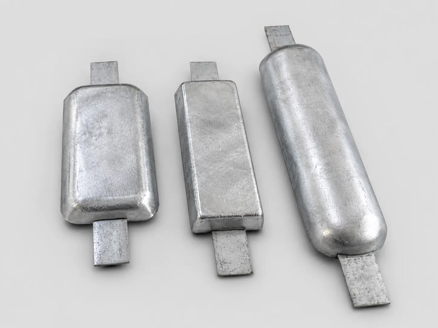
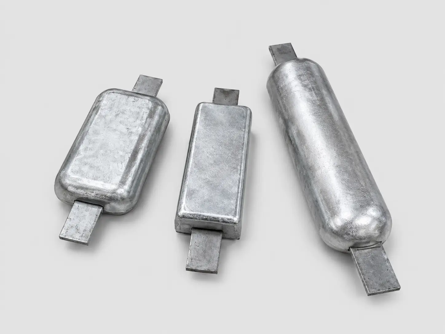
These images provide visual context for sacrificial anodes. They do not replace the approved drawing, specification, manufacturing route, inspection plan or order-specific evidence.