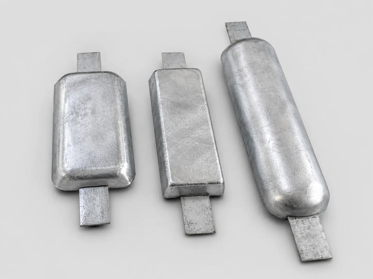
Aluminum Anodes
A common starting direction for selected seawater and offshore duties. Freeze alloy chemistry, electrochemical basis, insert, geometry and project acceptance.
Review Aluminum Anodes →

Galvanic Cathodic Protection · Project-Specific Selection
Aluminum, zinc and magnesium anode families reviewed against the electrolyte or soil, structure and coating, protection criteria, design current, life, alloy capacity, utilization, geometry, mounting and inspection scope.
Design boundary: an alloy name or anode weight is not a complete cathodic-protection design. Final material, quantity and placement require the asset, environment, coating, design current, output, life and governing criteria to be reviewed together.
A sacrificial anode is electrically connected to the protected structure while both are exposed to an electrolyte. The more active anode supplies protective current and is consumed preferentially. The complete system still depends on coating condition, continuity, isolation, placement, electrolyte and monitoring.
Relates current demand and time to usable alloy capacity, utilization and required net alloy mass.
Reviews driving voltage, anode resistance, geometry, spacing and environment against required current.
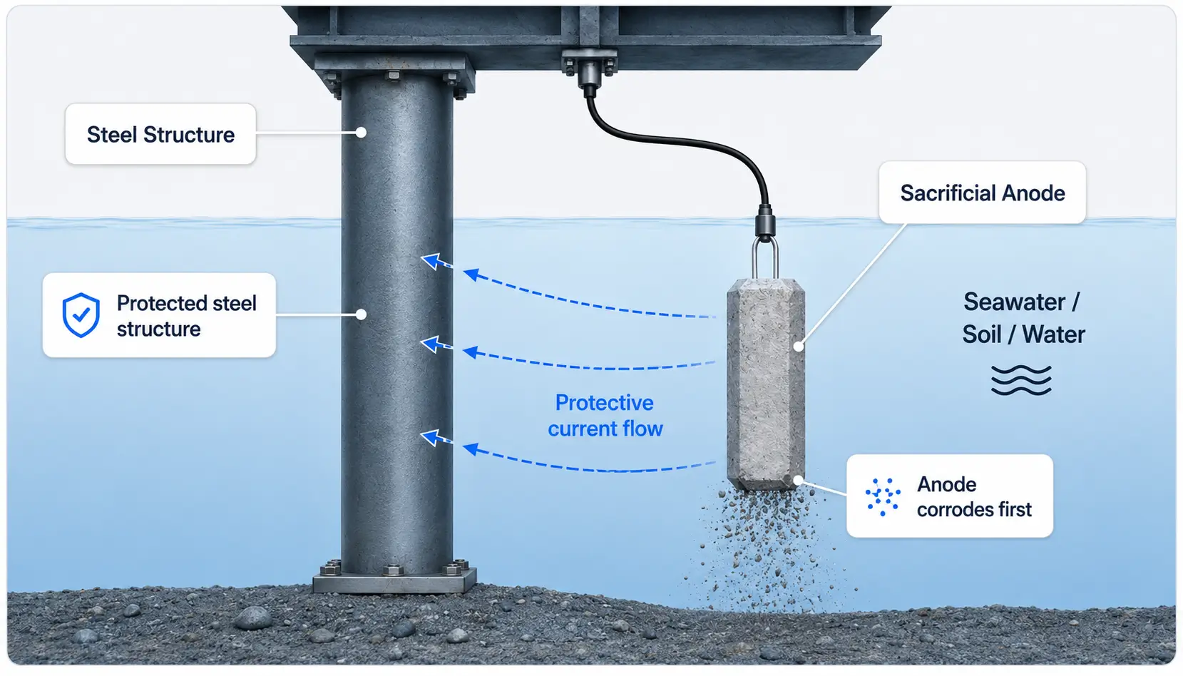
The parent page routes broad selection intent. Use the dedicated material pages for alloy-level detail and the approved project drawing for geometry, insert and mounting.
A common starting direction for selected seawater and offshore duties. Freeze alloy chemistry, electrochemical basis, insert, geometry and project acceptance.
Review Aluminum Anodes →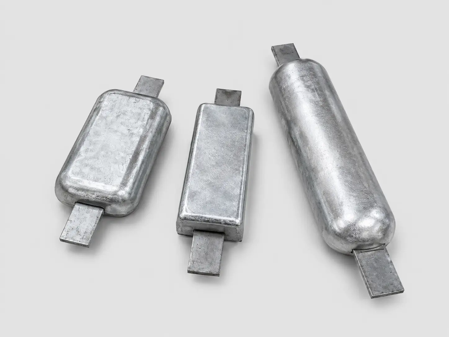
Used in seawater, brackish and other project-defined saline environments. Confirm composition, potential/capacity evidence, form and governing specification.
Review Zinc Anodes →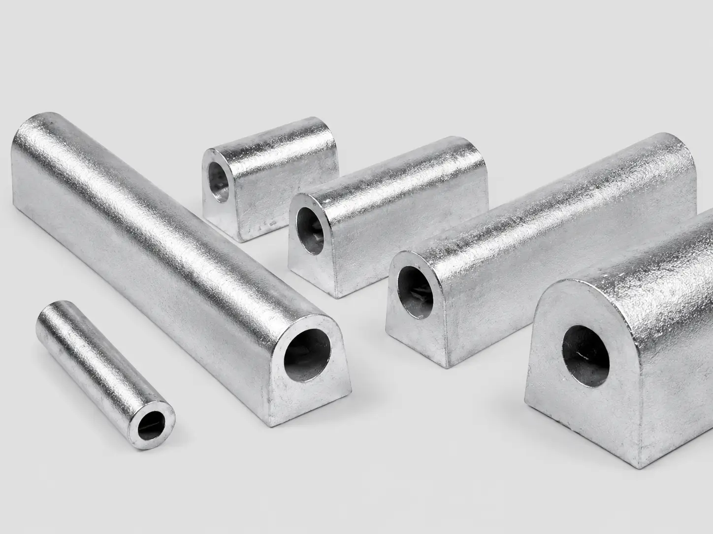
A starting direction for selected soil and freshwater or higher-resistance environments. Confirm alloy type, backfill where applicable and design basis.
Review Magnesium Anodes →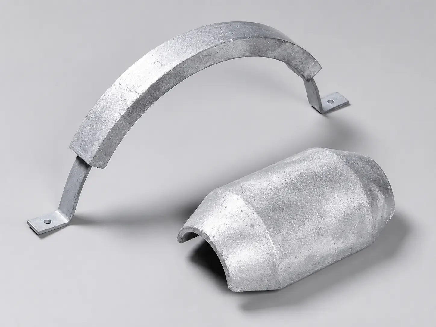
Pipeline and subsea configurations controlled by pipe OD, half-shell geometry, gap, inserts, welding or clamping boundary and installation method.
Review Bracelet Anodes →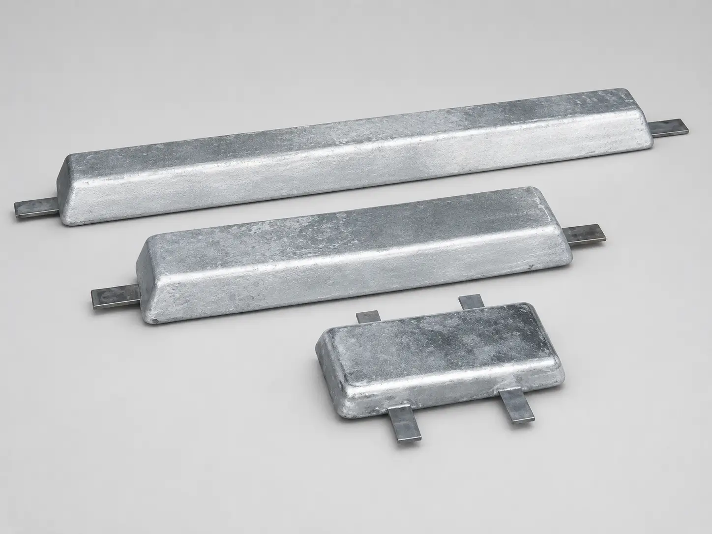
Weld-on, bolt-on or other drawing-defined hull configurations reviewed with coating, current distribution, location, hydrodynamic and replacement requirements.
Review Hull Anodes →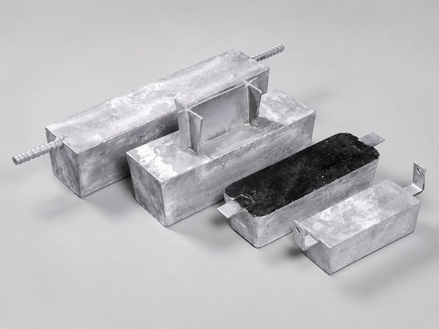
Tank layout requires coating condition, wetting cycle, structure area, current distribution, brackets, clearance and inspection access.
Review Ballast-Tank Anodes →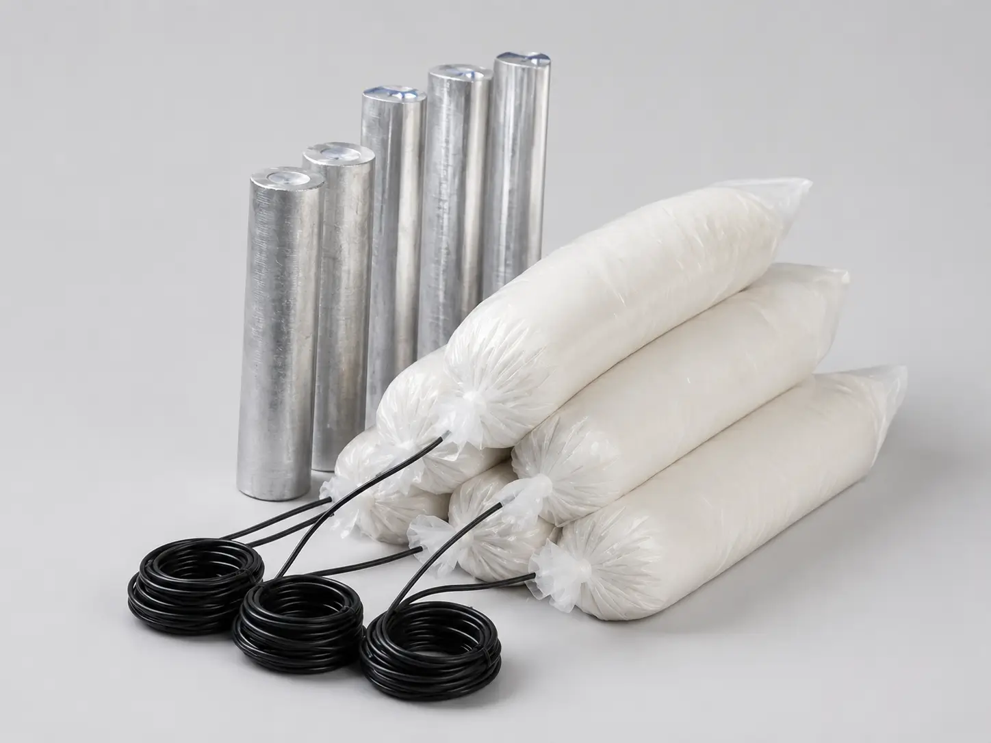
Packaged, distributed, stand-off or project-specific forms selected with soil/electrolyte data, coating and output calculations.
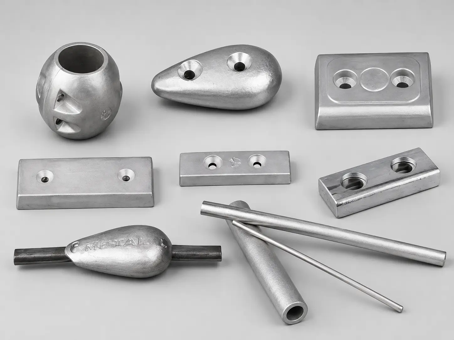
Cast or fabricated configurations with controlled net alloy mass, gross weight, insert/core, dimensions, tolerances, identification and release evidence.
Use the actual environment and governing project basis. The directions below are screening points, not a final design or universal compatibility statement.
| Material family | Common starting direction | Items to verify |
|---|---|---|
| Aluminum | Selected seawater, brackish and offshore duties | Alloy chemistry, temperature/salinity window, activation, capacity, potential, utilization and class/owner basis |
| Zinc | Seawater, brackish and selected saline environments | Composition/specification, environment, potential, capacity, passivation risk, geometry and evidence |
| Magnesium | Selected soil, freshwater and higher-resistance environments | Alloy type, potential basis, soil/resistivity, backfill, current output, interference and installation |
A useful RFQ states the inputs and the party responsible for the calculation. Unknown items should remain open rather than being replaced by a generic anode count.
Material, geometry, exposed/wetted area, coating type, age, breakdown and electrical isolation.
Seawater/brackish/freshwater or soil, resistivity, salinity, temperature, flow, depth and variability.
Criteria/reference scale, initial/maintenance/final current, design life, utilization and safety factors.
Placement, mounting, continuity, access, monitoring, replacement, standards, inspection and documents.
Net alloy mass supports the capacity calculation; gross weight may include the insert or core. State both, and link every physical requirement to the drawing revision.
| Characteristic | RFQ / PO definition | Evidence when ordered |
|---|---|---|
| Alloy | Material family, alloy designation, chemistry limits and applicable specification | Heat/batch composition and certificate |
| Electrochemical basis | Potential with reference scale, capacity, utilization and test/qualification basis | Order-defined report or certificate |
| Mass | Minimum/nominal net alloy mass and gross assembly weight with tolerances | Weight record and sampling plan |
| Insert / core | Material, size, position, preparation, exposure, weld or connection and pull/load duty | Drawing and inspection evidence |
| Geometry & mounting | Dimensions, tolerances, contact face, bracket/strap/cable, holes and installation interface | Approved drawing and dimensional report |
| Release scope | Visual acceptance, identification, traceability, inspection, class/third party and documents | ITP/MDR or agreed document package |
Application names help route the inquiry; they do not replace coating, environmental, electrical and installation data.
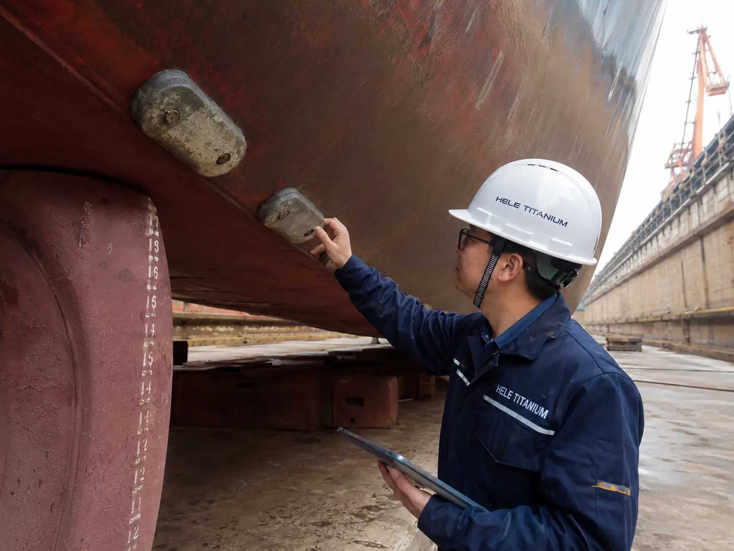
Define seawater/brackish range, coating, wetted area, protection criteria, operating profile, layout, mounting and class/owner requirements.
Review Marine Hulls & Ballast Tanks →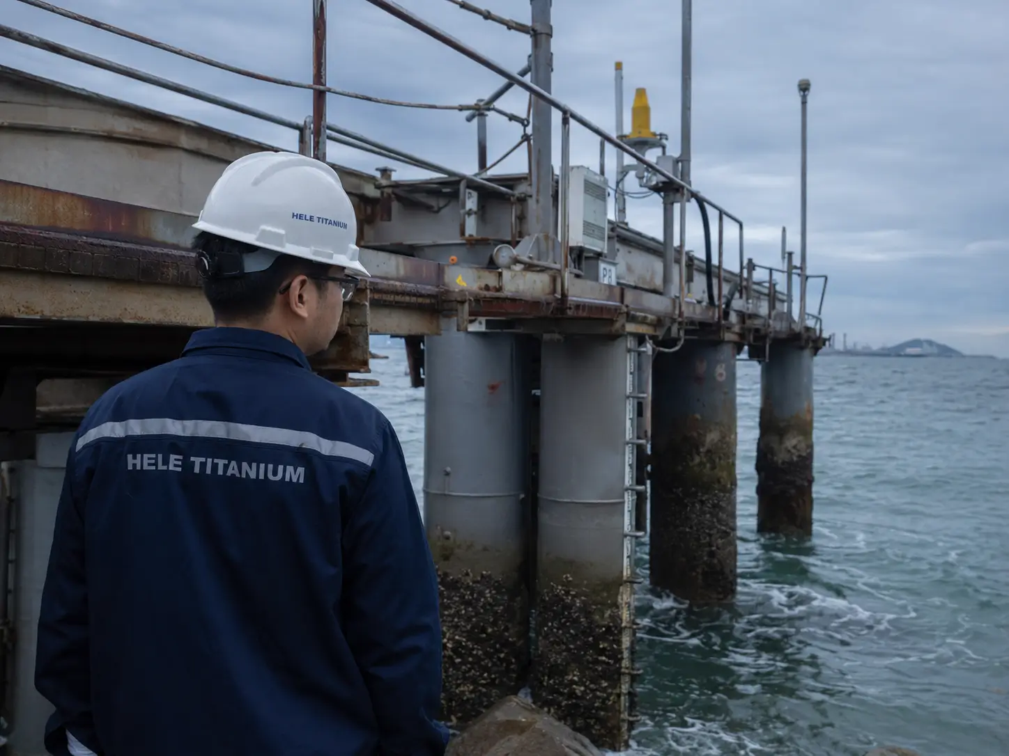
Define seawater depth/temperature, coating breakdown, exposed area, design life, current demand, structure continuity and installation/retrieval boundary.
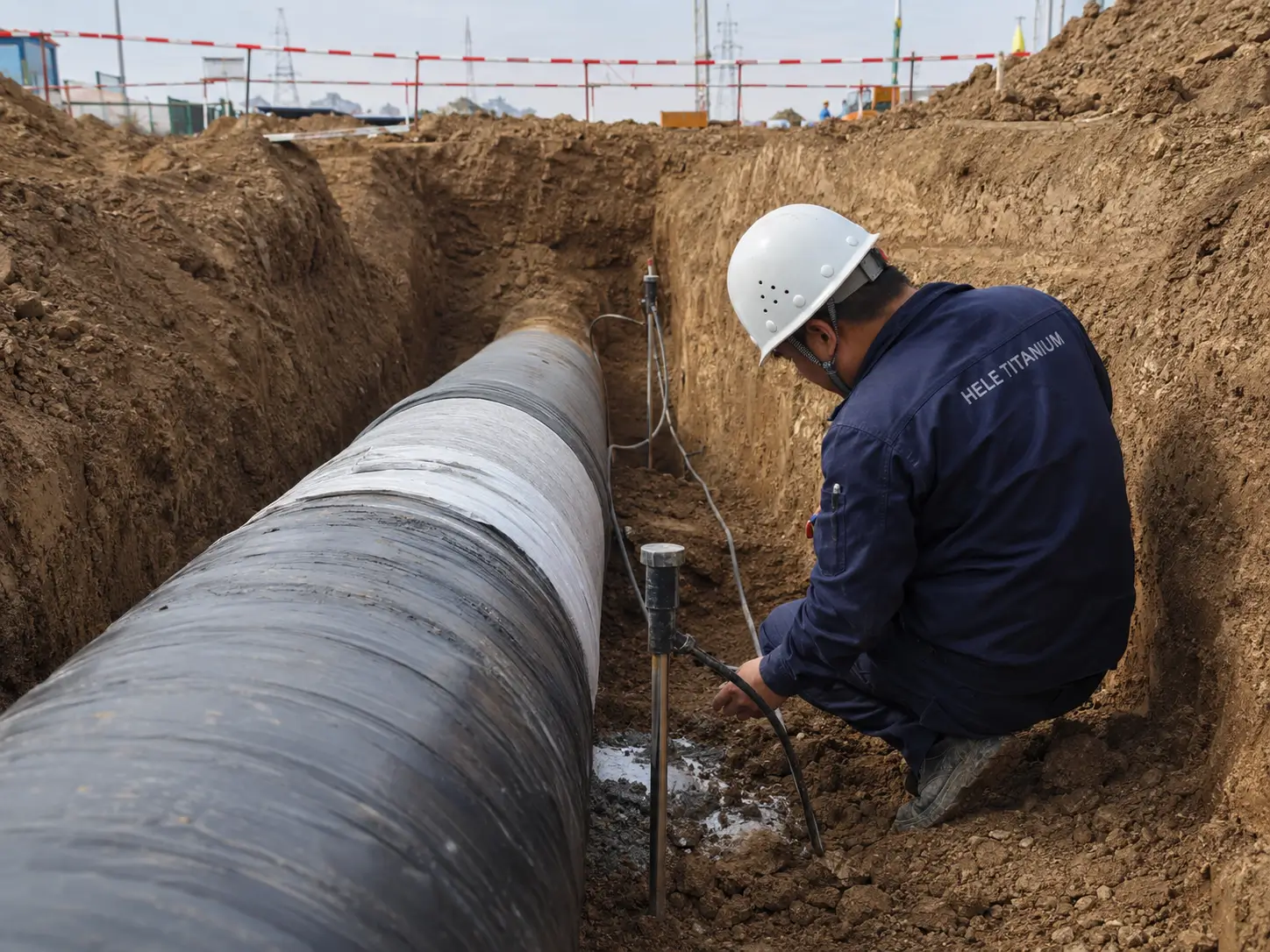
Provide coating system and age, soil/water resistivity, route conditions, isolation, test stations, design criteria and bracelet or groundbed layout.
Review Buried & Submerged Pipelines →
Define internal/external surface, water chemistry, level cycle, temperature, lining, isolation, access, placement and inspection/replacement plan.
Galvanic systems are driven by electrochemical potential difference and consume their anodes. ICCP uses an external DC source and a different anode, control and monitoring architecture. Neither is automatically superior.
A titanium MMO anode used with a rectifier is not a sacrificial aluminum, zinc or magnesium anode. The power source, anode consumption model, electrical design, monitoring and failure modes differ.
HELE can manufacture drawing-based sacrificial anodes around the ordered alloy, insert, net mass, geometry, mounting and inspection scope. Every physical and electrochemical requirement should remain traceable to the approved specification and drawing revision.
01 · Alloy Review
Confirm aluminum, zinc or magnesium family, alloy designation, chemistry limits, applicable specification and electrochemical qualification basis.
Typical order output: Approved alloy definition and required certificate basis.
02 · Insert & Core
Define insert or core material, preparation, position, exposure, welding or connection and any mechanical duty.
Typical order output: Controlled insert drawing and inspection points.
03 · Manufacturing Route
Control tooling, alloy charge, casting or fabrication route, visible acceptance, identification and drawing revision.
Typical order output: Order-linked manufacturing and traceability records.
04 · Mass & Geometry
Inspect net alloy mass, gross assembly weight, critical dimensions, tolerances, mounting features and insert exposure.
Typical order output: Weight and dimensional inspection records.
05 · Qualification
Coordinate chemistry, electrochemical, visual, dimensional, sampling, class or third-party requirements according to the order.
Typical order output: Specified test, inspection or qualification evidence.
06 · Lot Release
Link the product identity, heat or batch, drawing, inspection status, deviations and packing marks before shipment.
Typical order output: Release dossier and packing identification.
Anode manufacture does not replace the cathodic-protection design calculation. System life and protection depend on current demand, capacity, utilization, output, distribution, installation and the actual service environment.
Order rule: only the signed quotation, approved drawings, equipment or material schedule, inspection plan and responsibility matrix define the final HELE supply.
A weight or alloy name is not enough to compare sacrificial anodes. Freeze the environment, current-demand calculation, electrochemical capacity, utilization, output, insert and installation before comparing suppliers.
The anode is electrically connected to the protected structure while both share an electrolyte. The more active anode supplies protective current and is consumed preferentially. Coating condition, continuity, electrolyte and anode placement remain part of the system design.
There is no universal best alloy. Selection depends on electrolyte, resistivity or salinity, temperature, structure and coating, required current, design life, geometry, installation, standards and owner requirements.
No. Net anode alloy mass must be considered with alloy capacity, utilization factor, current demand, design time, anode resistance, output, geometry and distribution. Gross weight may also include an insert or core.
No. Mass supports capacity and life calculations, while current output also depends on driving voltage, electrolyte resistance, anode geometry, spacing, installation and structure potential. Both capacity and output checks are required.
No. Galvanic systems are self-powered by the electrochemical potential difference and consume the anode. ICCP uses an external DC source and a different anode/system architecture. A qualified CP designer should select the system.
Send the asset and environment, electrolyte or soil data, coating and exposed area, design code and life, current-demand basis, anode material, model/drawing, net and gross weight, insert and mounting, quantity, inspection, class and document requirements.
A drawing, calculation sheet, asset/coating schedule or existing-anode record is enough to begin. Unknown items can remain open rather than being replaced by a generic alloy or weight recommendation.
Prefer email?
sales@heletitanium.com